
Sealing appliance

a technology for sealing appliances and clips, applied in the field of sealing appliances, can solve the problems of inability to seal, risk of not taking place, and small clip size, and achieve the effect of simple and efficient manner

Inactive Publication Date: 2004-08-24
MERCK CHEM & LIFE SCI AB
View PDF6 Cites 74 Cited by
  • Summary
  • Abstract
  • Description
  • Claims
  • Application Information

AI Technical Summary

Benefits of technology

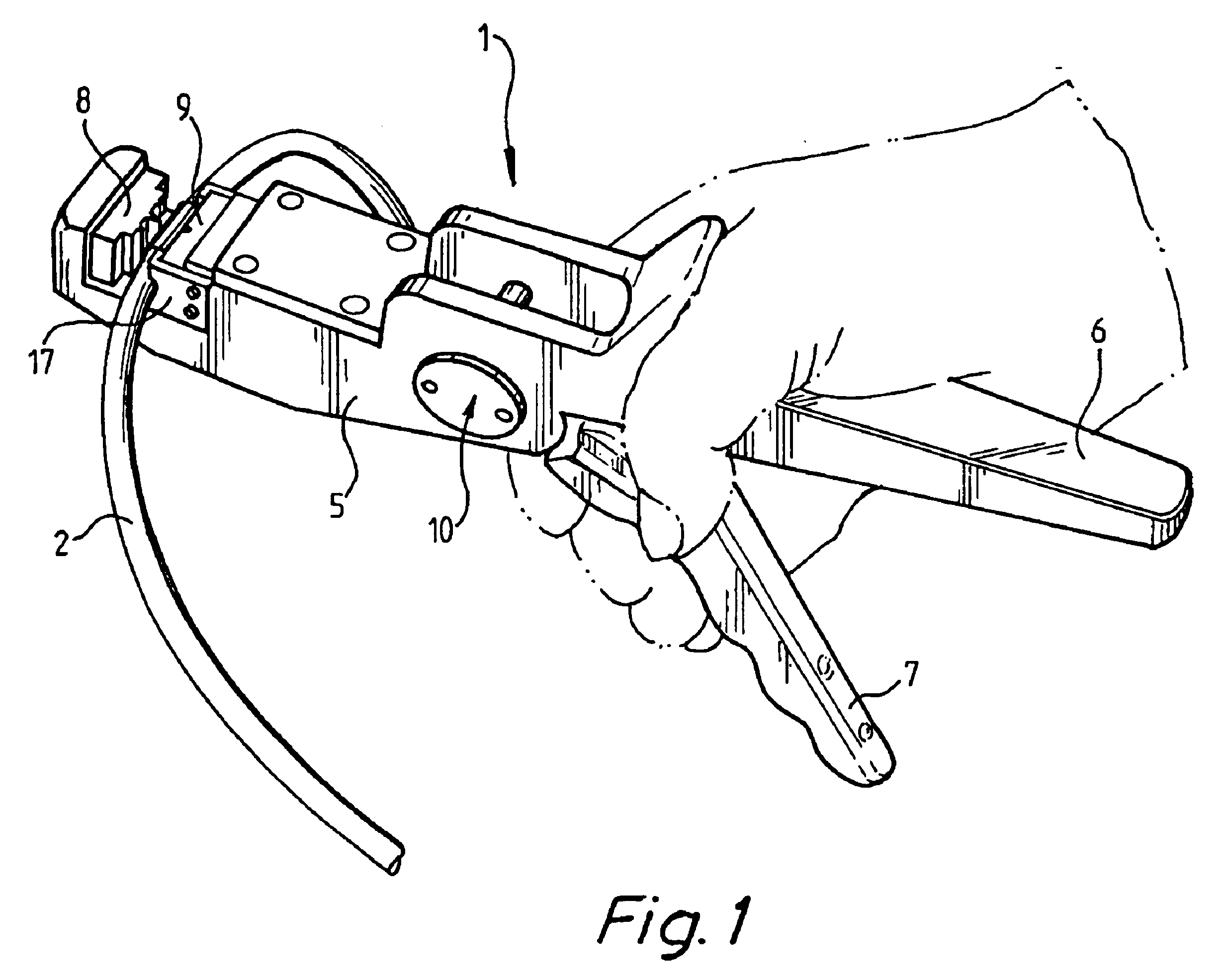
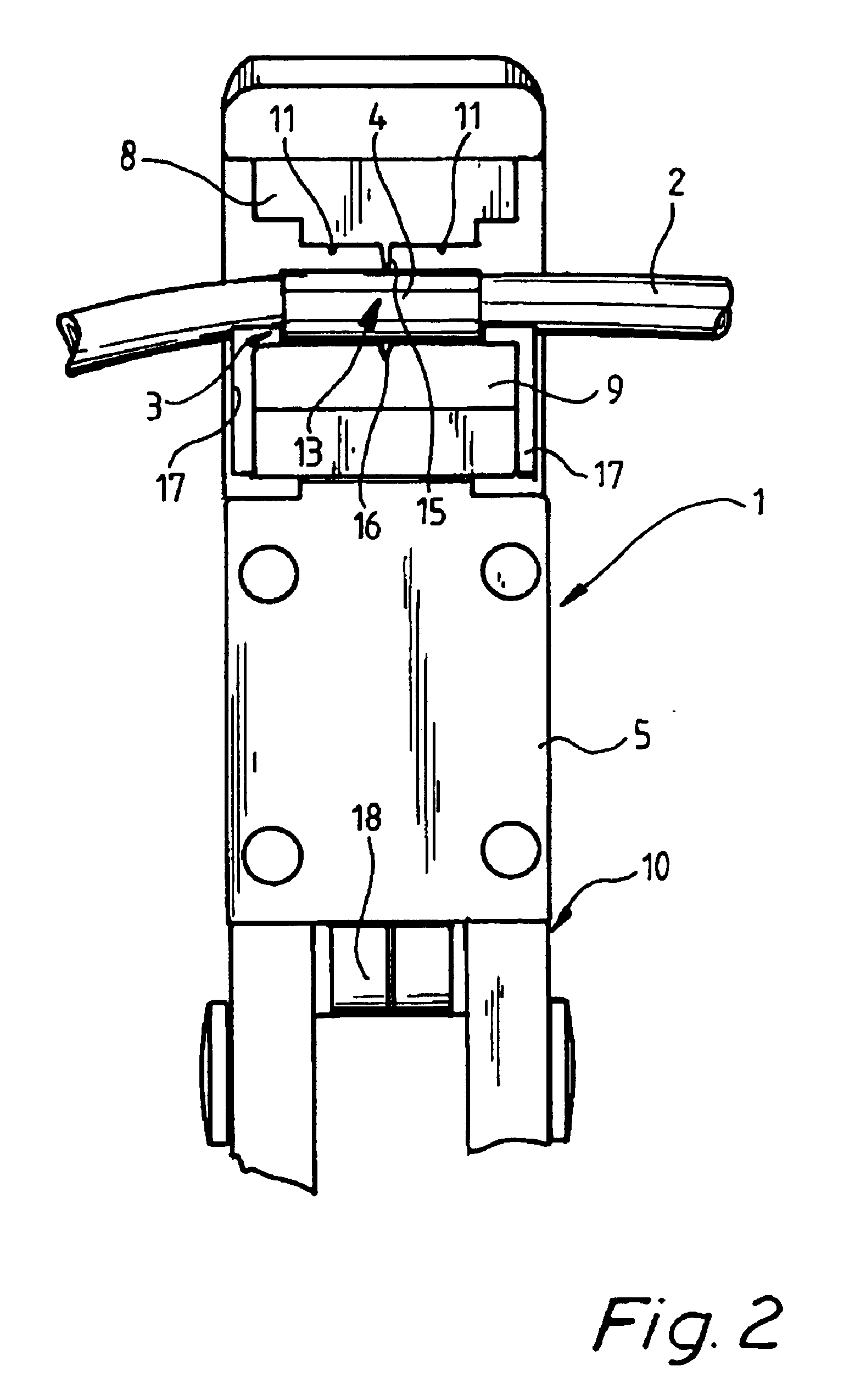
This as well as related objects are achieved in a simple and efficient manner in that the sealing means has the form of a sleeve which is slipped on to the hose, that at least one of the jaws has at least one bar which projects towards the other jaw and which, when the jaws are moving towards each other, makes an indentation in the sleeve and the hose to reinforce the sealing thereof as well as the fixing of the sleeve on the hose, and that at least one of the jaws has a cutting means, which projects towards the other jaw and which, when the jaws are moving towards each other, makes a cutting indication in the sleeve and the hose to allow a sealing cutting of the hose.

Problems solved by technology

As the relevant hoses have a relatively small diameter, say 5-10 mm, the clips are also relatively small and often difficult to apply in the right position on the folded end of the hose.
Nor is it infrequent that the clip falls off the end of the hose, before the sealing appliance has managed to grip it for crimping against the hose with the ensuing risk of sealing not taking place.
In the above use of the sealing appliance, which requires good hygienic conditions and contamination-free environment / surroundings, clips of the mentioned type are unacceptable.
One reason for this is that they are difficult to handle and often do not provide the desired sealing.
Another reason is that there is in most cases at least a small portion of the hose left downstream of the clip containing a small quantity of the medium which leaks out to the surrounding area with an obvious risk of contamination.

Method used


Image

  • Sealing appliance
  • Sealing appliance
  • Sealing appliance

Examples


Embodiment Construction

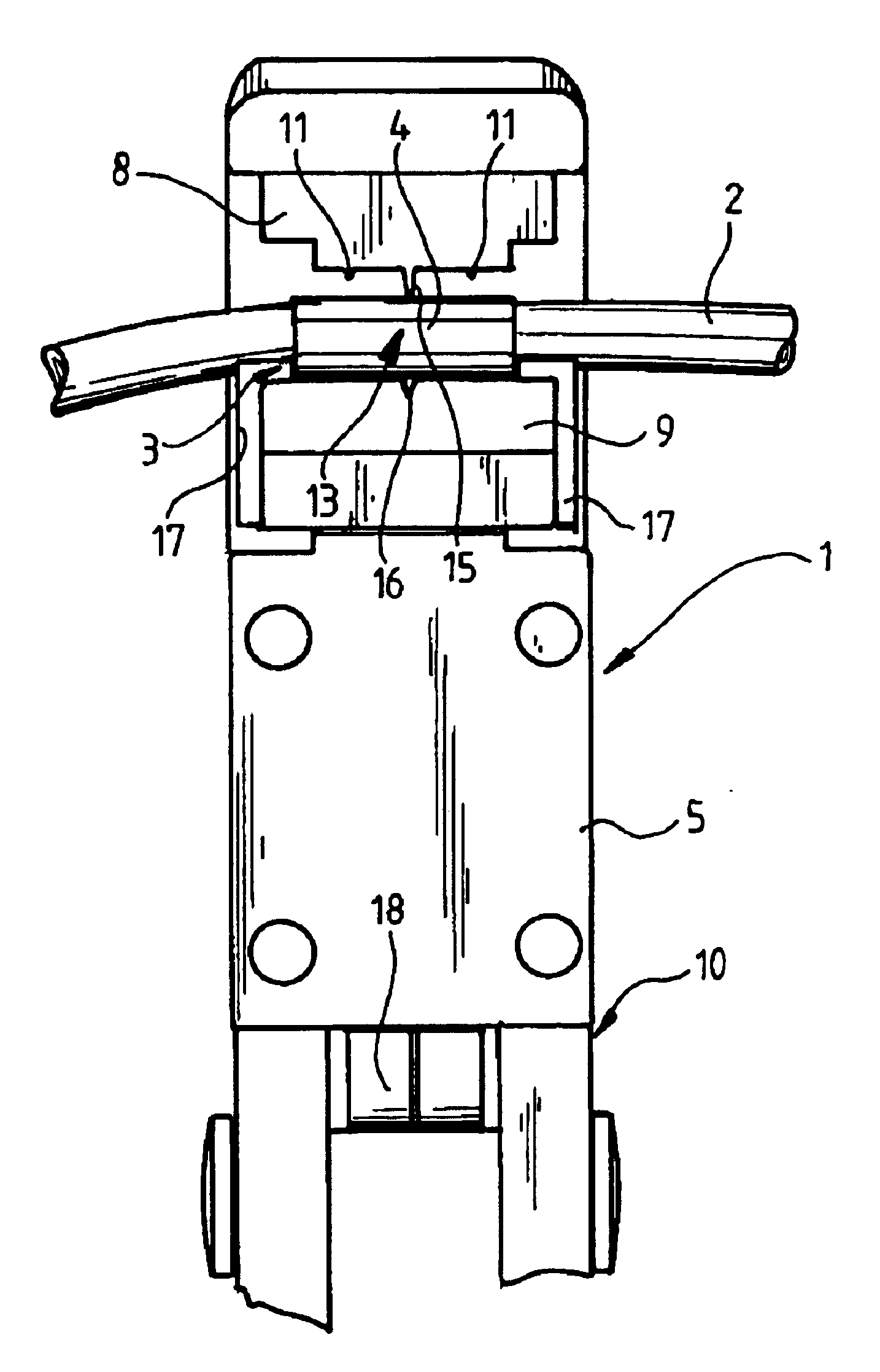
As mentioned above, the appliance generally designated 1 is primarily conceived for use in the type of device which is intended for introduction and / or withdrawal of a medium in a container and which is disclosed and described in WO 97 / 16715. More specifically, it is intended for sealing and cutting the hoses in a mechanical and contamination-free manner, which extend between the conveying means and the collecting vessels which are connected to the process container, so that the collecting vessels after being filled with a medium from the process container can be transported without any risk of contamination to a laboratory or the like for sampling or analysis of the medium.

Still, the appliance 1 can, of course, also be used in a number of other applications where good hygienic conditions and / or contamination-free surroundings and / or working environment are required to a varying extent.

Thus the appliance 1 is generally intended for mechanical sealing of hollow hoses 2 of elastic mat...


PUM

PropertyMeasurementUnit
diameteraaaaaaaaaa
elasticaaaaaaaaaa
distanceaaaaaaaaaa

Abstract

An appliance for sealing elastic hoses with a sleeve, which is plastically deformable and slipped onto the hose, has two jaws which are movable towards and away from each other. One jaw has two straight bars which project towards the other jaw and extend transversely of the sleeve to make two transverse indentations in the sleeve and the hose when the jaws are moving towards each other. The same jaw has a cutting edge which projects towards the other jaw and is directed transversely of the sleeve, the cutting edge making a substantially transverse cutting indication in the sleeve and the hose when the jaws are moving towards each other.

Description

The present invention relates to an appliance for mechanical sealing of hollow hoses of elastic material with a sealing means which is made of plastically deformable material and which is applied to the hose, said appliance having two jaws, which are movable towards and away from each other and which, when moving towards each other, crimp the sealing means against the hose to seal the same.In a prior-art sealing appliance of the type mentioned by way of introduction, the sealing means in the form of a folded clip is applied to a likewise folded end of the hose. The clip is then crimped against the hose to seal the same, after which the hose is cut downstream of the clip by means of a pair of scissors or some other cutting tool.As the relevant hoses have a relatively small diameter, say 5-10 mm, the clips are also relatively small and often difficult to apply in the right position on the folded end of the hose. Nor is it infrequent that the clip falls off the end of the hose, before ...

Claims


Application Information

Patent Timeline
Patent Type & Authority Patents(United States)
IPC IPC(8): B29C65/02B29C65/74B29C57/10B29C57/00B01L3/00B25B9/00B23D21/00B29C65/64G01N1/18
CPCB23D21/006B25B7/20B29C57/10B29C65/743B29C66/8614G01N1/18B29C65/562B29C66/1122B29C66/4312B29C66/81435B29C66/81431B01L3/505A61B10/0096Y10T156/1052B01L2200/0689B01L2300/0838B29C65/64B29L2009/00B29L2023/007B29C66/5344B29C66/81417Y10T156/1005Y10T29/49925Y10T29/53657Y10T156/18Y10T156/1313Y10T156/1378B29C66/8322B29C66/8221B29C66/8242Y10T83/0596Y10T83/8821B29C66/857A61M39/146B29C66/861C03B11/086C03B2215/11C03B2215/26C03B2215/32
Inventor ARTHUN, NILS
Owner MERCK CHEM & LIFE SCI AB
Learn More