
System and method for real-time library generation of grating profiles

a library and profile technology, applied in the field of dimensions in gratings, can solve the problems of slow method, difficult implementation, and increasing difficulty in measuring these sub-micron features

Inactive Publication Date: 2004-07-27
TOKYO ELECTRON US HOLDINGS INC
View PDF6 Cites 203 Cited by
  • Summary
  • Abstract
  • Description
  • Claims
  • Application Information

AI Technical Summary

Problems solved by technology

Measurement of these sub-micron features is increasingly difficult as the size of the features become smaller.
This method is slow, expensive, and only provides one measurement number seen from the top of the feature.
Again, this is difficult to implement because of the setup required.
This process is time consuming and expensive even for a limited library of profiles of grating dimensions and the associated spectrum data of reflected light.
An extensive library of profiles and spectrum data would however be inefficient for searching purposes needed for real-time work.

Method used


Image

  • System and method for real-time library generation of grating profiles
  • System and method for real-time library generation of grating profiles
  • System and method for real-time library generation of grating profiles

Examples


Embodiment Construction

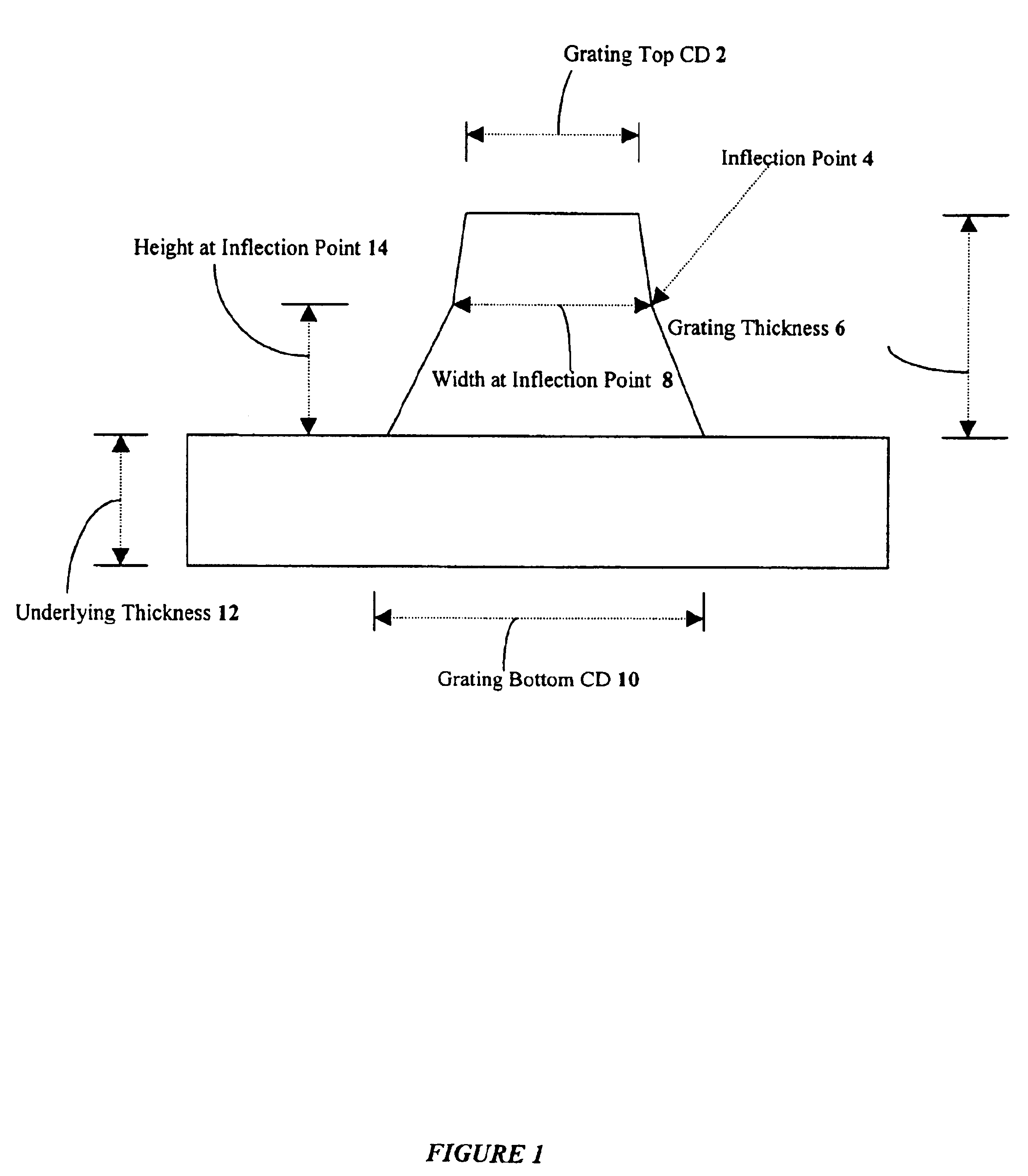
FIG. 1 is an architectural diagram illustrating the critical dimensions (CD) of a grating feature in one embodiment of the present invention. The cross-sectional view of a feature in a grating has a grating top CD 2, grating bottom CD 10, a grating thickness 6, and underlying thickness 12. Other dimensions are the width at inflection point 8 and the height at the inflection point 14. The inflection point 4 is the point in the sidewall of the feature where the slope changes. The percent height at inflection point is defined as the ratio of the height at inflection 14 to the grating thickness 6. Some applications may include other feature measurements such as the magnitude of T-topping, footing, rounding, undercut, concave sidewalls, and convex sidewalls as well as the angle of intersection of the sidewall and the underlying thickness.

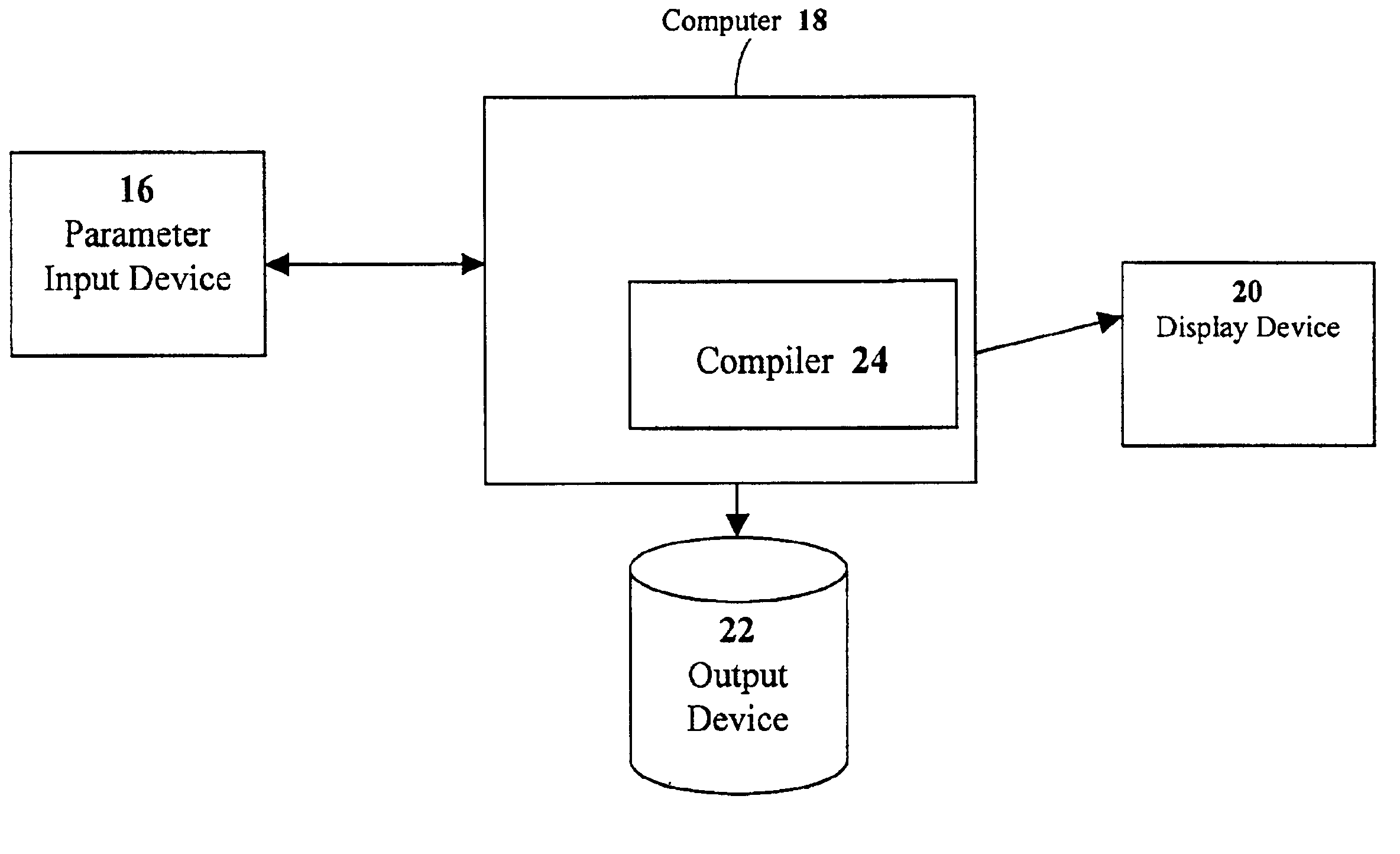
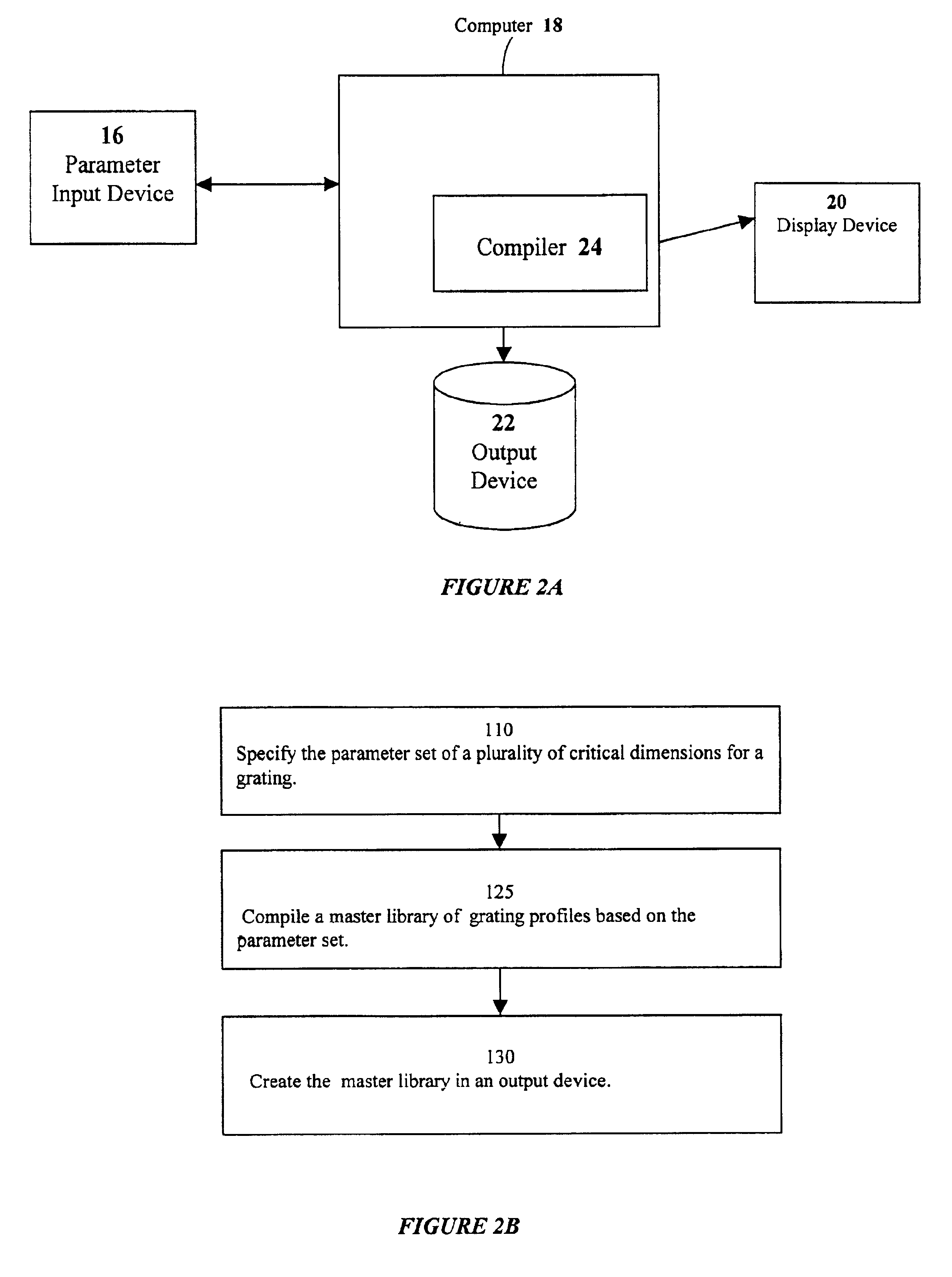
FIG. 2A is an architectural diagram illustrating the compilation of a master library of grating profiles in one embodiment of the present invention. Par...


PUM


Abstract

The present invention provides a method and a system for a real-time configurable definition and generation of grating profile libraries. A parameter set is used to specify the ranges of grating dimensions and resolutions of the profile library to be generated. In one embodiment, a compiler creates subsets of a large profile library, the subset designed to enable rapid search and validation of real-time data. In another embodiment, an automatic process generates a new parameter set and a new subset of the library when trigger conditions are met. Subsets of the profile library may be used to check if grating spectrum data are within the ranges established for an application and if the dimensions are within the process averages established for a manufacturing run. The system for generation of grating profile libraries is scalable, operable in a distributed environment, and includes application specific items that can be selected or determined by the client.

Description

BACKGROUND OF INVENTION1. Field of InventionInvention relates to the measurement of dimensions in gratings and more particularly to the generation and use of configurable libraries of grating profiles.2. Description of Related ArtFeatures on semiconductor devices and transmitters of optical fiber links are being formed that are less than one micron in width. Measurement of these sub-micron features is increasingly difficult as the size of the features become smaller. However, knowledge of the dimensions of gratings or periodic structures is essential in order to determine if the dimensions of the features are within the acceptable ranges and if a particular fabrication process causes the sidewalls of the features to be tapered, vertical, T-topped or undercut.Traditionally, a sample was cleaved and examined with a scanning electron microscope or similar device. This method is slow, expensive, and only provides one measurement number seen from the top of the feature. Angular scatterom...

Claims


Application Information

Patent Timeline
IPC IPC(8): G02B5/18G06N5/00G06N5/02G06F17/30
CPCG02B5/1847
Inventor JAKATDAR, NICKHILLAUGHERY, MICHAEL
Owner TOKYO ELECTRON US HOLDINGS INC
Learn More