
Medical ventilator system

a ventilator and medical technology, applied in the field of medical ventilators, can solve the problems of increasing the amount of time needed increasing the amount of time necessary and not significantly reducing the amount of time required to wean the patient from the medical ventilator, so as to achieve the effect of reducing the amount of time required

Inactive Publication Date: 2004-07-13
UAB RES FOUND +1
View PDF17 Cites 92 Cited by
  • Summary
  • Abstract
  • Description
  • Claims
  • Application Information

AI Technical Summary

Benefits of technology

The present invention is a medical ventilator system that overcomes the shortcomings of previous devices. It includes a source of pressurized oxygen connected to the patient through a fluid conduit or breathing tube, with a valve that adjusts the amount of oxygen support for the patient. The ventilator system also has a controller that monitors the patient's oximeter reading and adjusts the valve accordingly to maintain the optimal oxygen support. The controller can calculate the amount of change in oxygen support using a preset formula or fuzzy logic based on the patient's oximeter reading. This ventilator system not only provides safe and effective ventilation support but also helps to wean the patient from the ventilator more quickly.

Problems solved by technology

Such systems, however, are disadvantageous not only since they require extensive medical attention by medical personnel, but are inherently inaccurate.
Such inaccuracies increase the amount of time necessary to wean the patient from the ventilator system.
While these previously known automated ventilation systems have effectively reduced the amount of required medical attention for the patient, they have not significantly reduced the amount of time necessary to wean the patient from the medical ventilator.

Method used


Image

  • Medical ventilator system
  • Medical ventilator system
  • Medical ventilator system

Examples


Embodiment Construction

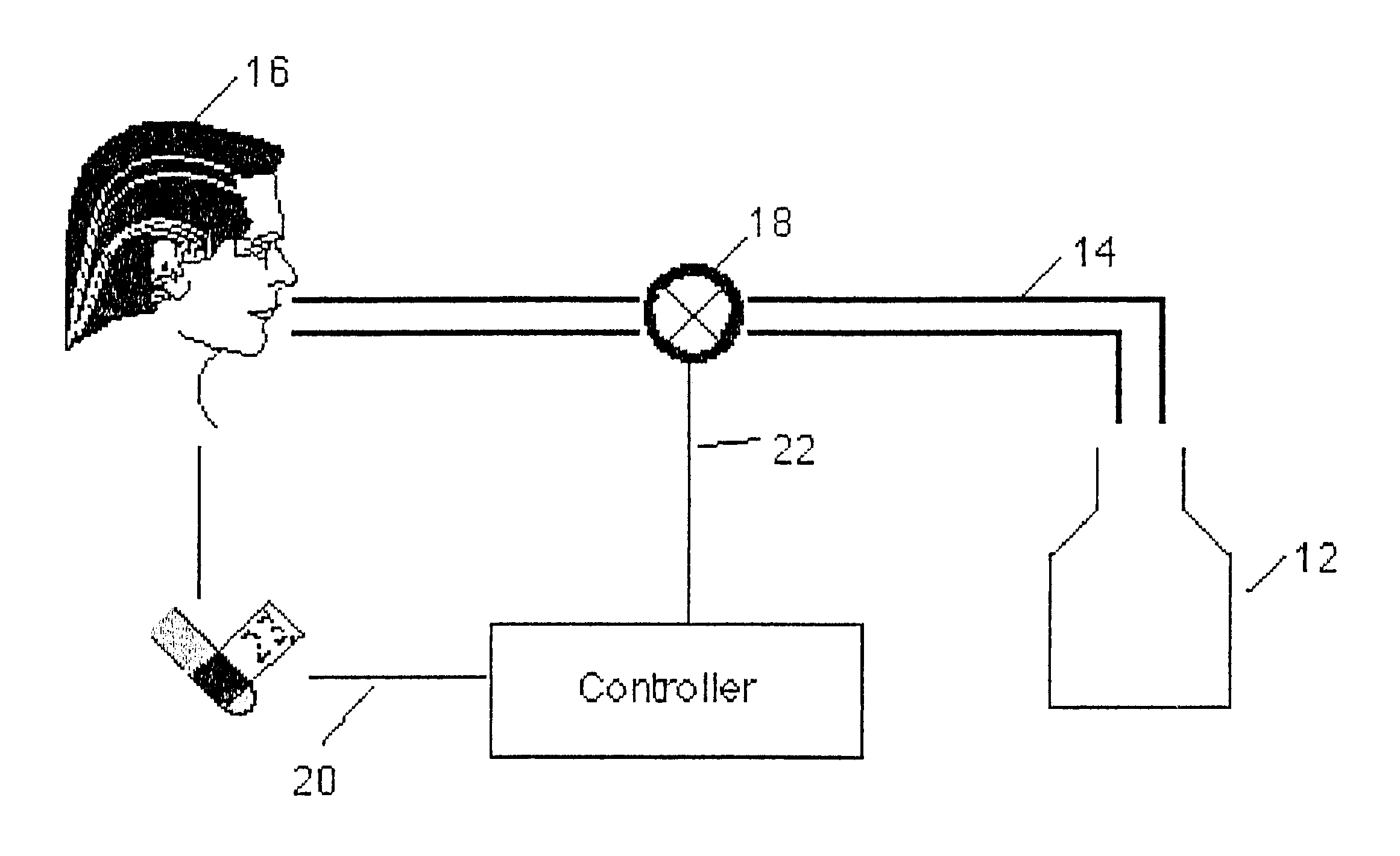
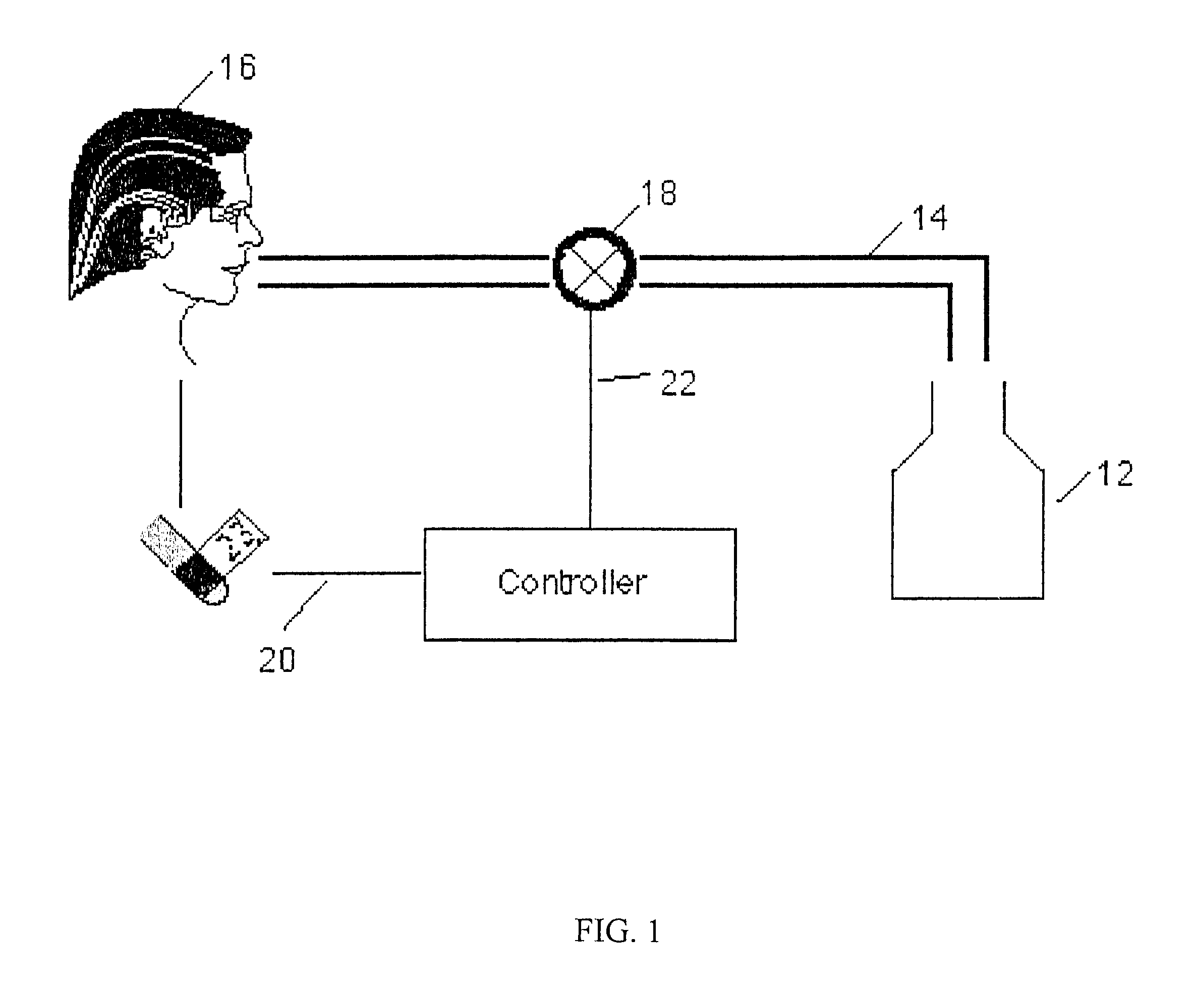
With reference first to FIG. 1, a diagrammatic view of a preferred embodiment of the invention is there diagrammatically illustrated. The ventilator system 10 includes a source 12 of pressurized oxygen which is fluidly connected by a fluid conduit 14 to a patient 16. A valve 18 is fluidly connected in series with the fluid conduit 14. This valve 18 is variably actuatable to thereby vary the fraction of positive pressure inspired oxygen (FiO.sub.2) support for the patient.

A microprocessor based controller 20 controls the actuation of the valve 18 through a control line 22. Any appropriate interface, such as an RS-232 interface, is provided between the processor 20 and the valve 18. Furthermore, the controller 20 receives a signal representative of the arterial oxygen saturation (SpO.sub.2) from a pulse oximeter 23 attached to the patient 16 through an input line 24.

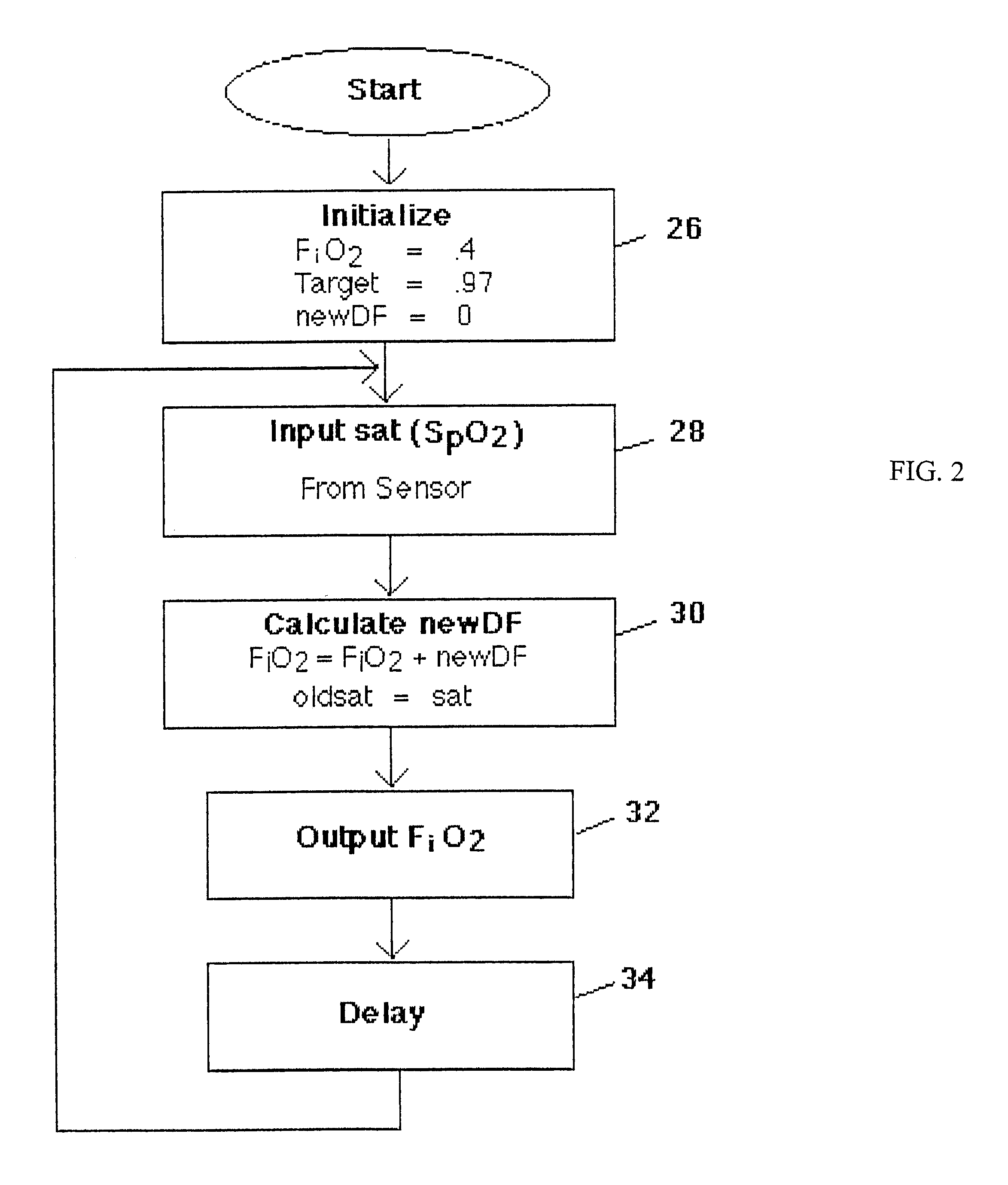
With reference now to FIG. 2, the main loop of a program executed by the controller 20 to control the FiO.sub.2 support ...


PUM


Abstract

A medical ventilator system is disclosed which automatically controls and modifies the oxygen support provided to the patient. The system includes a source of pressurized oxygen and a fluid conduit extending between the pressurized oxygen source and a patient. A valve is fluidly connected in series with the conduit which is variably controllable to vary the oxygen support for the patient. A pulse oximeter provides an SpO2 signal representative of the blood saturation of the patient. A controller is responsive to the magnitude of the SpO2 signal as well as the rate of change of the SpO2 signal for varying the oxygen support (FiO2) to the patient by variably actuating the valve. Preferably, the controller utilizes fuzzy logic to determine the proper oxygen support for the patient.

Description

I. Field of the InventionThe present invention relates generally to medical ventilators.II. Description of the Prior ArtMedical ventilator systems have been long used to provide supplemental oxygen support to patients unable to breathe normally on their own accord. These previously known medical ventilators typically comprise a source of pressurized oxygen which is fluidly connected to the patient through a fluid conduit.A variably actuatable valve is connected in series with the fluid conduit to vary the fraction of positive pressure inspired oxygen (FiO.sub.2) to the patient. FiO.sub.2 will vary between 0.21, in which no supplemental oxygen support is provided to the patient, and 1.0, in which pure oxygen is provided to the patient.In order to determine the proper FiO.sub.2, the arterial oxygen saturation (SpO.sub.2) is typically monitored via a pulse oximeter attached to the patient. The SpO.sub.2 is ideally in the range of 0.97-1.0 whereas an SpO.sub.2 of less than 0.91 is dange...

Claims


Application Information

Patent Timeline
Patent Type & Authority Patents(United States)
IPC IPC(8): A61M16/00A61M16/12A61M16/10
CPCA61M16/00A61M16/12A61M2016/1025A61M2230/205A61M16/024
Inventor STRICKLAND, JR., JAMES H.
Owner UAB RES FOUND
Learn More