
Thrust bearing and method for equalizing load

a technology of bearings and bearings, applied in the direction of bearings, shafts and bearings, rotary bearings, etc., can solve the problems of excessive cost of pads and supporting hardware, mechanical linkages that require considerable axial space, and contact points of linkages subject to wear and tear

Inactive Publication Date: 2004-06-08
PIONEER MOTOR BEARING
View PDF8 Cites 38 Cited by
  • Summary
  • Abstract
  • Description
  • Claims
  • Application Information

AI Technical Summary

Benefits of technology

"The present invention provides an improved thrust bearing that can equalize the load on the thrust pads and is not limited by the manufacturing tolerances, misalignment, shaft flexibility, or wear. The thrust bearing uses hydrodynamic pressure generated in a lubricant by the rotation of the journal over the surface of the pad. The thrust bearing also includes a pad carrier with a pad-carrying surface, a sealing-plate surface, and a carrier structure defining a lubricant manifold, pressure equalization passages, and at least two thrust pads. The thrust pads have a pad structure defining a bearing surface and a rear pad surface with at least a portion of which communicates with one of the pressure equalization passages. The rear pad surface may define a rear pad recess. The invention provides an improved thrust bearing assembly with a receptacle containing a lubricant and the thrust bearing immersed in the lubricant."

Problems solved by technology

The equalization of mechanically-pivoted thrust pads typically involves tight tolerancing, mechanical linkages, or flexible members, which introduce several disadvantages into the design.
Tight tolerancing may add excessive cost to the pads and supporting hardware and is only an approximate means of equalization.
Mechanical linkages require considerable axial space and are known to lock-up, ceasing to provide equalization under high loads or certain forms of dynamic loads.
Furthermore, the contact points of the linkages are subject to wear.
Flexible members are subject to wear at the contact points and have the potential for fatigue failure.
Thus, there remains uneven load equalization on all pads.
With respect to load equalization, mechanical designs of conventional thrust bearings are subject to contact fretting, deformation, and wear, or to fatigue damage.
Mechanical designs are further limited in their ability to respond to dynamic changes in relative pad loading.
The current use of hydrostatic suspension for the load equalization of tilting-pad thrust bearings is limited to individual pads, which again does not accommodate dynamic changes in relative pad loading.

Method used


Image

  • Thrust bearing and method for equalizing load
  • Thrust bearing and method for equalizing load
  • Thrust bearing and method for equalizing load

Examples


Embodiment Construction

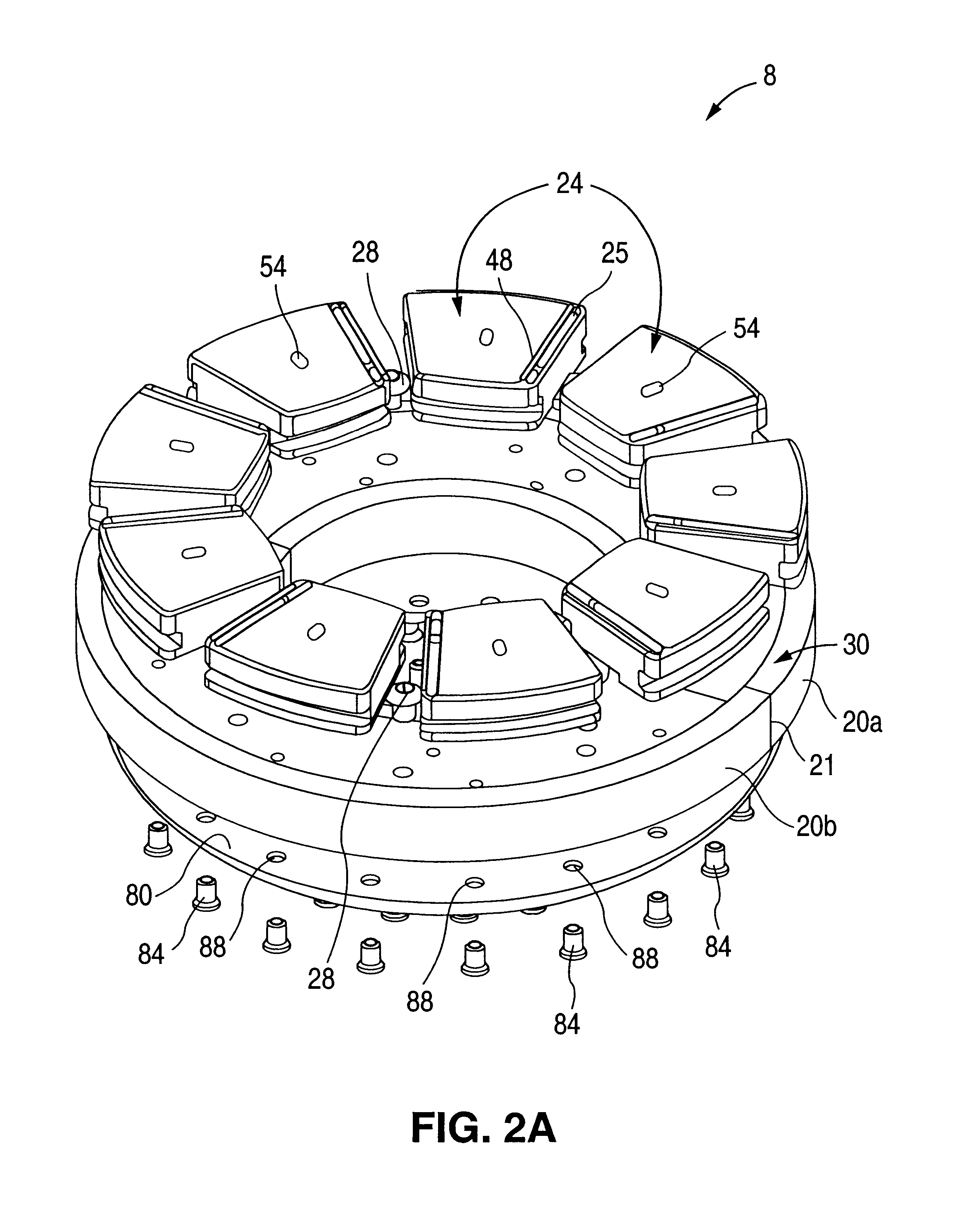
Referring in detail now to the drawings wherein similar parts of preferred embodiments of the invention are identified by like reference numerals, there is seen a thrust bearing, generally illustrated as 8, including a carrier ring 20 supporting a plurality of thrust pads 24 as best shown in FIG. 2A. Thrust pads 24 are prevented from rotating with the relatively-rotating load surface by an equal plurality of stop pins 28. Stop pins 28 are fixed in a plurality of bores 32 in the carrier ring 20, as best seen in FIGS. 2A, 3 and 10. The carrier ring 20 also includes an oil inlet 34 as best shown in FIG. 13, a plurality of oil equalization passages 46, an equalization manifold 42 (e.g., a semi-circular groove in vertical cross-section as best seen in FIG. 5A and FIG. 9) communicating with the plurality of oil equalization passages 46 by respective oil equalization passages 46 terminating in the equalization manifold 42, an oil inlet manifold 38 (e.g., a parallelogramic channel in vertic...


PUM


Abstract

A multi-pad, fluid film thrust bearing has the pads suspended from the carrier ring on hydrostatic oil pressure regions. The oil is pressurized hydrodynamically by relative rotation between a load surface and the bearing surface of each pad; and the oil is passed through each pad to a rear cavity where the hydrostatic pressure region is established. A manifold interconnects all of the hydrostatic pressure regions for the individual pads in order to average the hydrostatic pressures and provide for static and dynamic load equalization.

Description

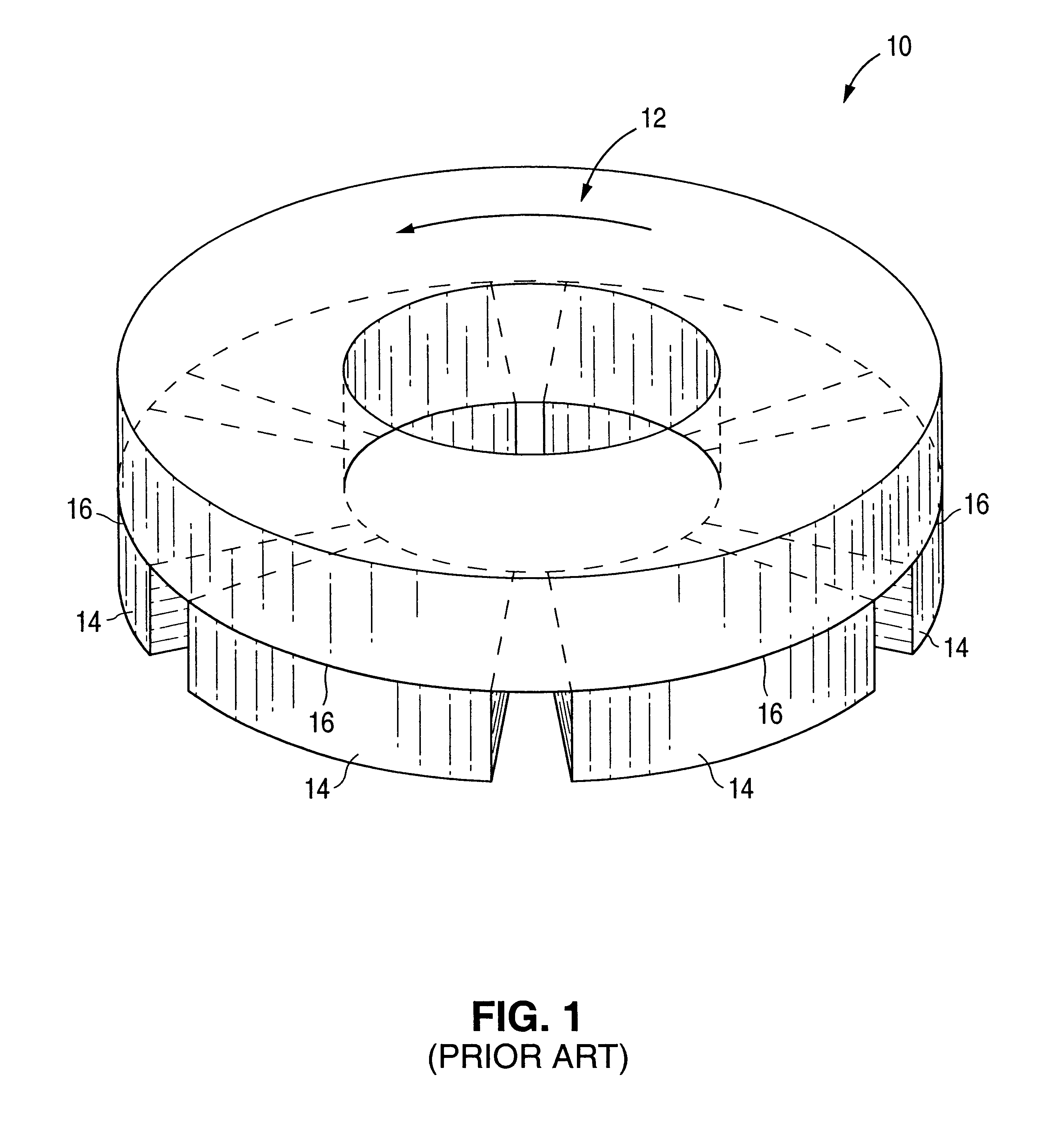
1. Field of the InventionThe present invention relates to thrust bearings. More particularly, the present invention provides a thrust bearing of the type comprising a pad carrier coupled to an annular series of discrete thrust pads having respective thrust bearing surfaces against which rotatably bears a co-operating annular bearing or load surface of a rotating member. More particularly further, the present invention also provides a method for equalizing a load on the thrust pads.2. Description of the Prior ArtThere is seen in FIG. 1 a prior art end-thrust bearing, generally illustrated as 10. The end-thrust bearing 10 includes a collar 12 supporting a plurality of stationary segments 14. The segments 14 in the actual bearing are pivoted in order to allow them to assume slightly different angles by which to create different degrees of convergence of respective oil films 16. The collar 12 is attached to a rotating member (not shown). Oil is introduced at the inner edges of the segme...

Claims


Application Information

Patent Timeline
Patent Type & Authority Patents(United States)
IPC IPC(8): F16C32/06F16C17/06F16C17/04
CPCF16C17/06F16C32/0651F16C32/0666F16C32/0692
Inventor BRANAGAN, LYLE ARTHUR
Owner PIONEER MOTOR BEARING
Learn More