
Vertical ecosystem structure

a vertical ecosystem and structure technology, applied in the field of construction, can solve the problems of slowing down the deterioration process of arable lands, loss of arable land, and loss of fertile lands, and achieve the effect of quick and inexpensive assembly

Inactive Publication Date: 2004-04-27
CHICK NELSON HYDE
View PDF31 Cites 51 Cited by
  • Summary
  • Abstract
  • Description
  • Claims
  • Application Information

AI Technical Summary

Benefits of technology

"The present invention relates to the field of construction and the incorporation of vegetation and man made structures. The technical effects of the invention include the ability to build structures that are cost-effective, environmentally friendly, and aesthetically pleasing. The invention also provides various methods for incorporating vegetation into man made structures, such as rooftop gardens, vegetation friendly retaining walls, and freestanding structures with integrated vegetation. These methods allow for the growth of vegetation in urban settings and provide benefits such as reducing greenhouse gases, filtering air pollutants, and creating private spaces. The invention also addresses the challenge of integrating vegetation into man made structures by incorporating vegetation into load-bearing walls and providing a structural load bearing capacity."

Problems solved by technology

Due to the rapid urbanization of the 20.sup.th century, there has been a substantial loss of these fertile lands, and there are three factors mentioned below that may slow down the deterioration process of these arable lands.
The challenge for builders will be to build structures that are inexpensive to build and can prevent the loss of arable land in urban settings.
One disadvantage to these devices is the added expense of building a roof that can sustain the added weight of the vegetation and the means of sustaining that vegetation.
Another disadvantage is the added maintenance of having to re-roof these roofs more often than a conventional roof.
A disadvantage to this patent is the limitation on how large the root ball of the vegetation can be which limits the growth to the vegetation.
All four mentioned patents have the disadvantage of being able to use only a limited number of vegetation species.
Unfortunately retaining walls are not freestanding and cannot be used as a structural component for a freestanding structure.
This limits its utility, to only structures that retain hillsides.
Unfortunately, these walls cannot be used as a structural component for man made structures.
These walls can only hold up their own weight and the vegetation encased in these walls.
This method also creates an aesthetically pleasing environment, but there are some problems with this method.
It takes decades for a structure to be enveloped by vegetation.
This method is also limited because only a small number of species of vegetation are suitable for use with this method.
The disadvantage of this method is that the vegetation is isolated and cannot form an integrated ecosystem.
One disadvantage of this method is a limited number of species of vegetation can be used.
Another limitation of this system is that it cannot be used as a load-bearing component of a structure.
This system would also be more expensive to build than a system that incorporates vegetation as it is built because this system would be an additional step in the building process of a structure.
All the earlier mentioned strategies for incorporating more vegetation into a man made structure lack a structural load bearing capacity.
All five of the previously mentioned patents can be used for a load bearing component of structure but none have a capacity to incorporate vegetation into a structure.

Method used


Image

  • Vertical ecosystem structure
  • Vertical ecosystem structure
  • Vertical ecosystem structure

Examples


Embodiment Construction

. 1 TO 9

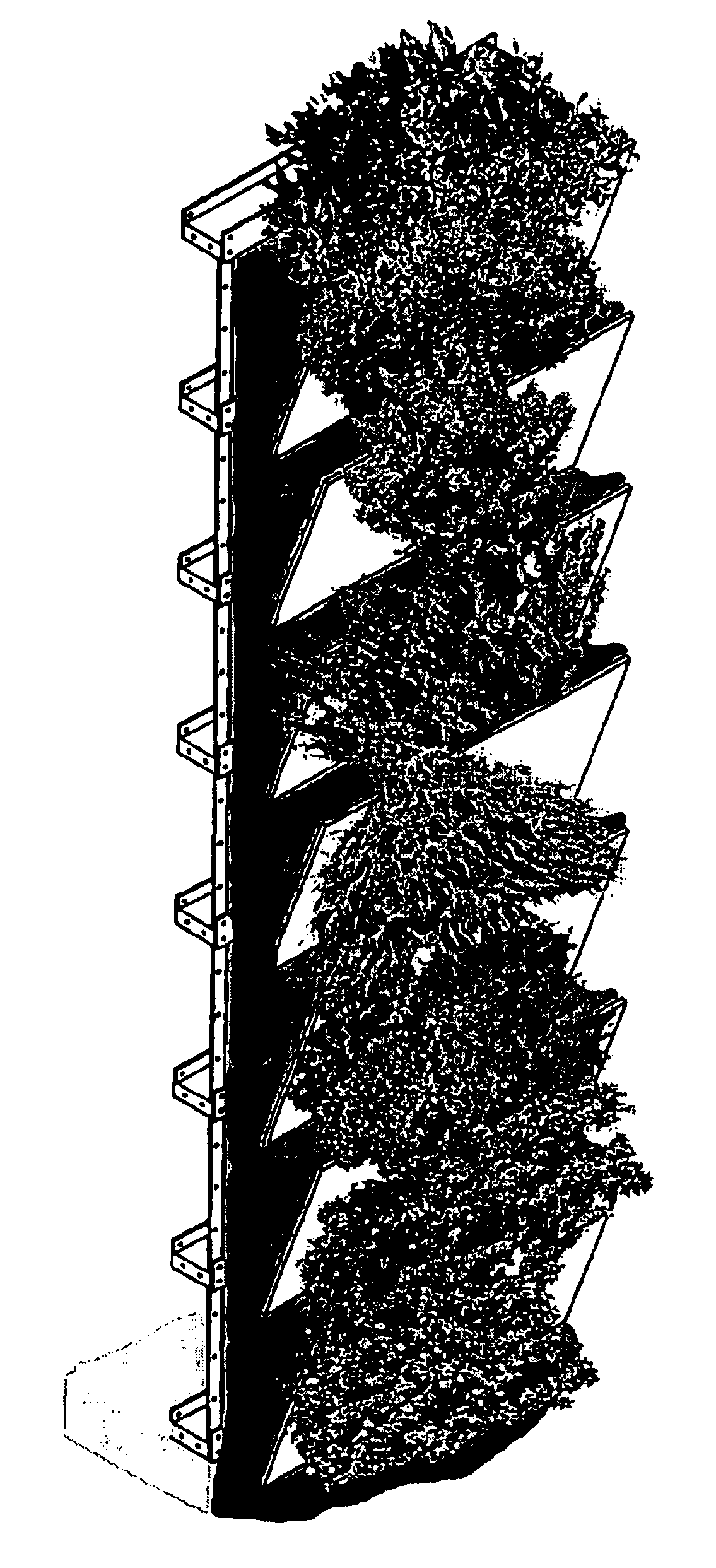
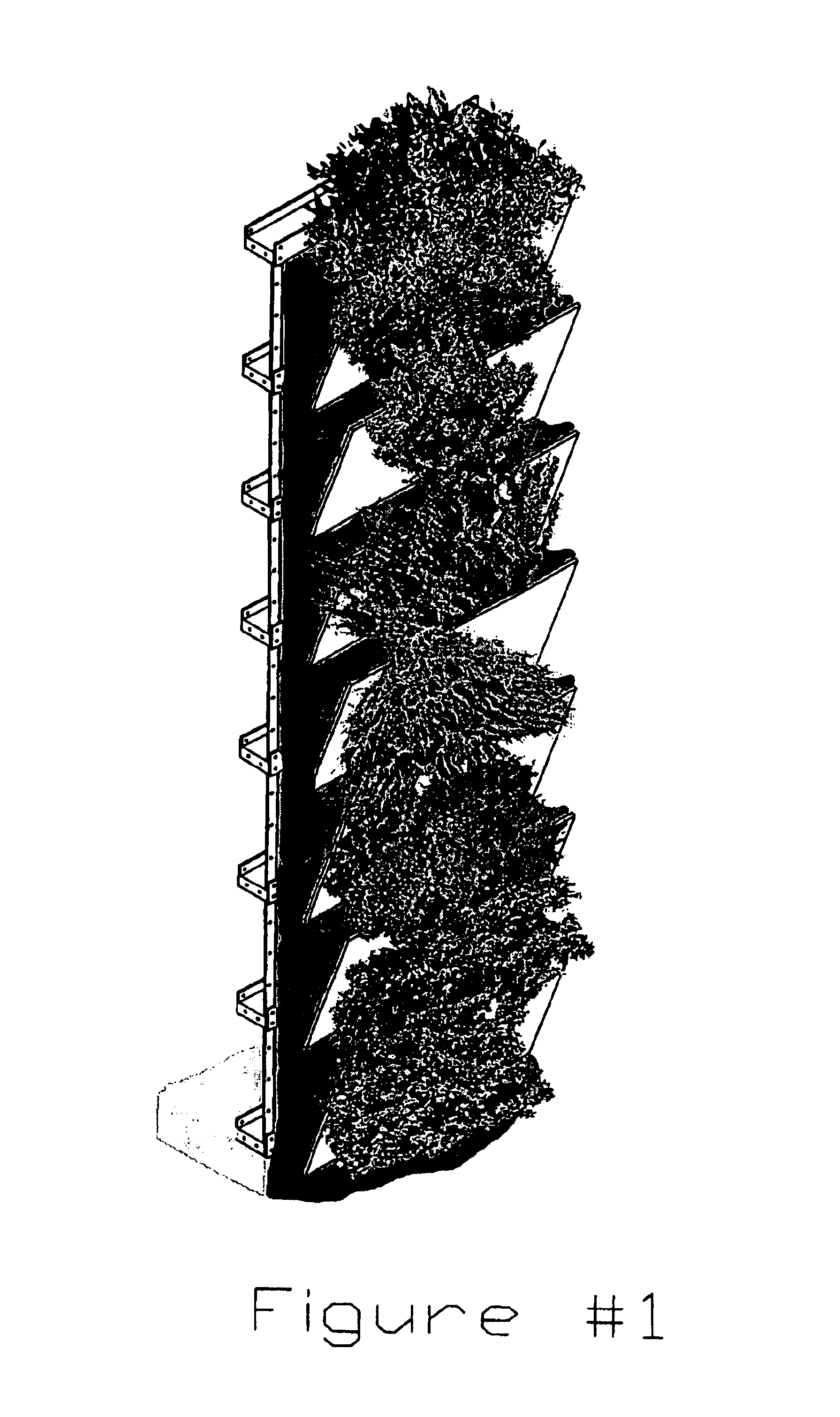
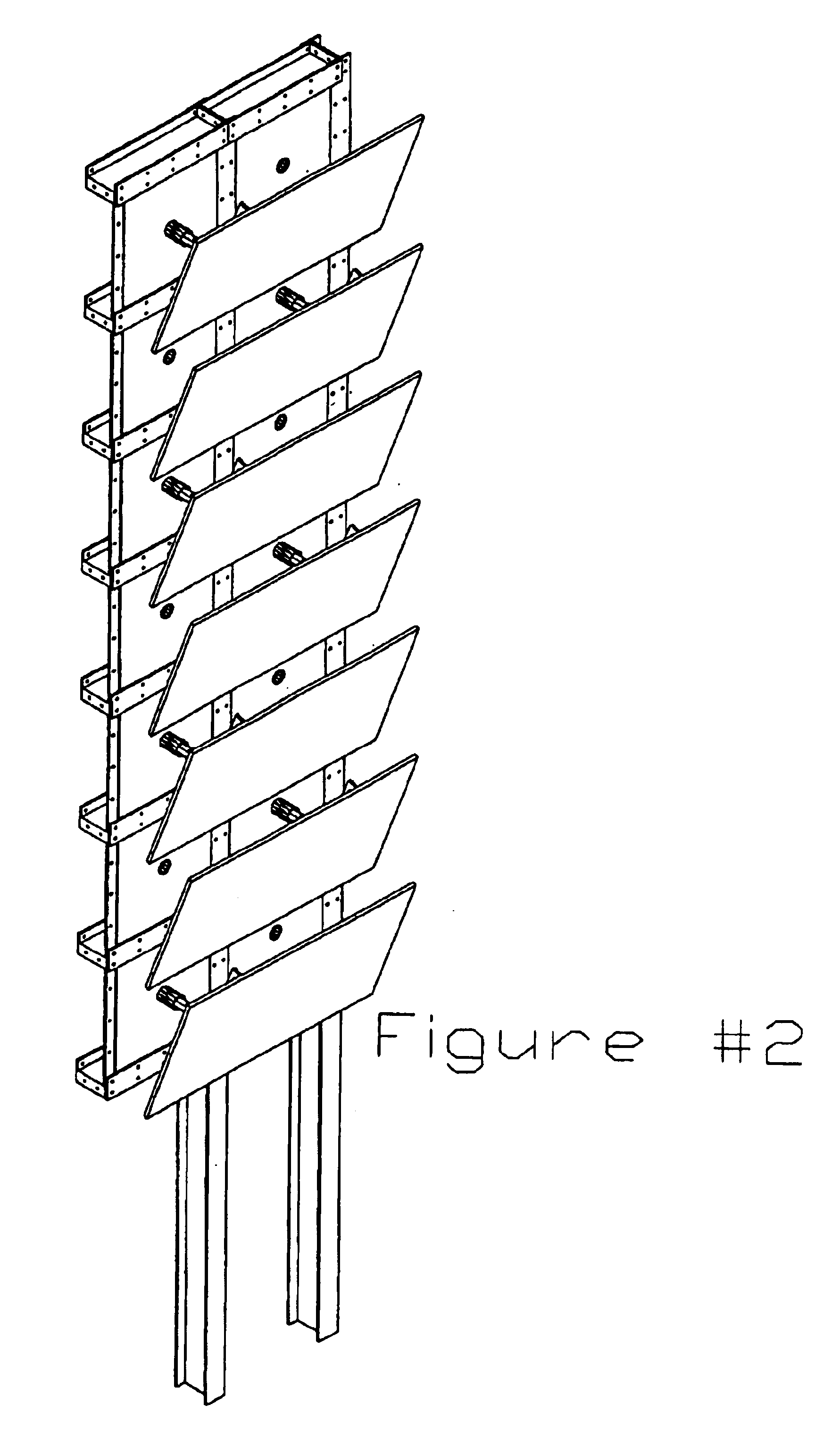
There follows a description of the preferred embodiments of the invention by reference to the accompanying drawings. Referring now to FIG. 1 there is a perspective view of the wall structure of the present invention as it would be seen after it was built and vegetation had integrated itself with the wall.

This patent's method of construction for the main structural component can be built using two types of materials. This method can be built with either rigid steel components or molded from concrete with reinforcement steel embedded in the concrete. Concrete can either be poured on site or components manufactured elsewhere and assembled on site. Every finished structural wall using this method of construction is comprised of a grid on its face. Each grid forms one cell and every cell has an identical structure to all cells that comprise a structure using this method of construction. Each cell has one or more passages between sides of a structural wall that use this method of ...


PUM


Abstract

A main structure that can be constructed using either solid steel assembly (32) or reinforced concrete assembly (33) acts as the main structural component for new and remodel construction. The main structure whether it uses reinforced concrete assembly (33) or steel assembly is comprised of cells of equilateral size and each cell has a passage between inner and outer wall created using this method of construction. The inner wall uses the passages to secure accompanying structures and systems to a wall that use this structural system. The outer wall uses the passages to secure retaining assembly (34) to the structure. Retaining assembly (34) holds a strata of soil to the wall and creates plateaus along face of outer wall. The plateaus created by securing retaining assembly (34) to main assembly's (32) or (33) give vegetation a place to be planted and secured to a wall that incorporate the construction method of this invention. The passages between the inner and outer walls also nurture the vegetation attached to a structure built using this invention's method of construction by allowing direct access to the roots. By allowing direct access to the roots of the vegetation planted on a structure utilizing the construction method of this invention each plant can receive the optimum amount of irrigation, drainage, and fertilizer.

Description

1. Field of InventionThe present invention relates to the field of construction, and more particularly to the erection of walls that withstand vertical and horizontal loads. The present invention also relates to environmental protection by incorporating nature as an integrated component of man made structures.2. Prior ArtMost urban centers are located on prime arable land. Due to the rapid urbanization of the 20.sup.th century, there has been a substantial loss of these fertile lands, and there are three factors mentioned below that may slow down the deterioration process of these arable lands.Vegetation created on these arable lands converts carbon dioxide to oxygen. An increase in vegetation in an urban setting can reduce the amount of greenhouse gases which could help reduce global warming.Vegetation filters air pollutants.An increase of vegetation in an urban setting gives the psychological benefit to urban inhabitants of having access to nature filled environments.As mankind's ...

Claims


Application Information

Patent Timeline
Patent Type & Authority Patents(United States)
IPC IPC(8): A01G9/02E01F8/02
CPCE01F8/027A01G9/025Y02P60/20
Inventor CHICK, NELSON HYDE
Owner CHICK NELSON HYDE
Learn More