
Self adjusting mechanism for locking plier, wrench, or other tool

a self-adjusting mechanism and locking technology, applied in the direction of wrenches, pliers, manufacturing tools, etc., can solve the problems of slow manipulation of the adjustment screw, frustrating the user, and nearly impossible to make the adjustment one hand

Inactive Publication Date: 2004-03-23
BLACK & DECKER INC
View PDF10 Cites 20 Cited by
  • Summary
  • Abstract
  • Description
  • Claims
  • Application Information

AI Technical Summary

Problems solved by technology

One major disadvantage to known locking pliers it that the adjusting screw, while effective, is slow to manipulate.
The time required to perform this operation can be frustrating to the user.
In addition, it is nearly impossible to make this adjustment one handed, requiring one hand to hold the plier while the other turns the adjusting screw.
Such pliers exist, but typically have their own drawbacks.
This location is difficult to access, the knob is relatively small, and turns in the opposite direction from what would be expected.
The result is a plier which provides less than satisfactory performance.

Method used


Image

  • Self adjusting mechanism for locking plier, wrench, or other tool
  • Self adjusting mechanism for locking plier, wrench, or other tool
  • Self adjusting mechanism for locking plier, wrench, or other tool

Examples


Embodiment Construction

The disclosed invention is described below with reference to the accompanying figures in which like reference numbers designate like parts.

Overview

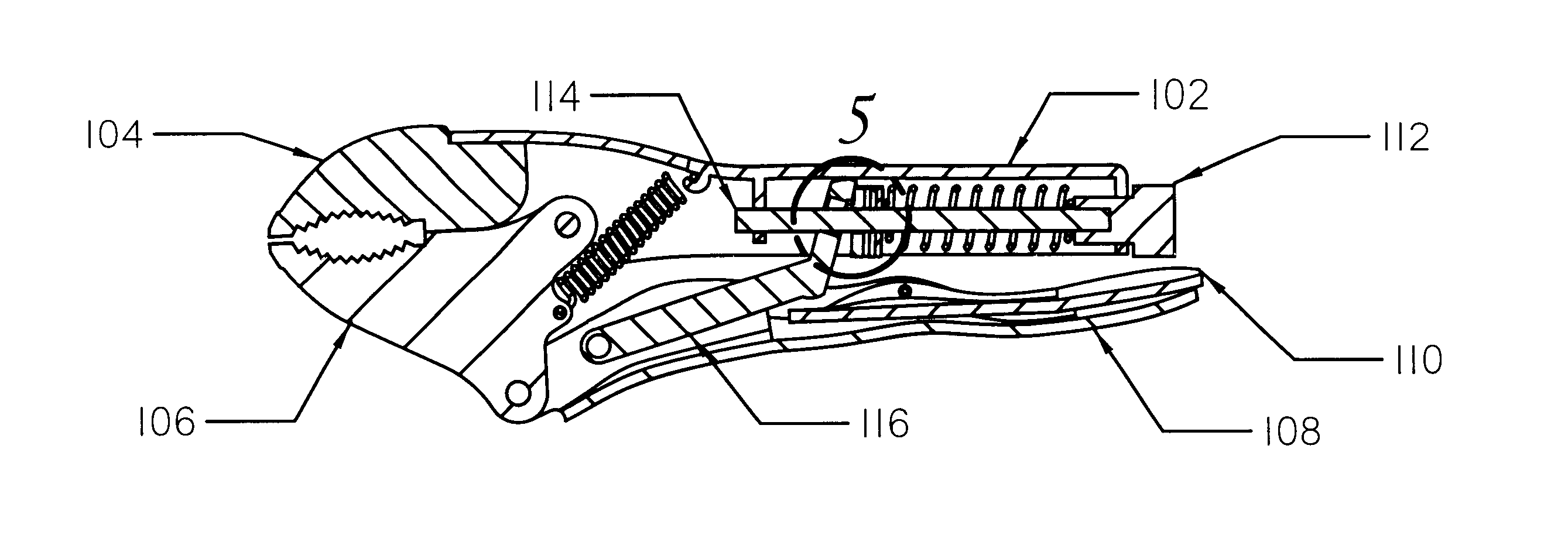
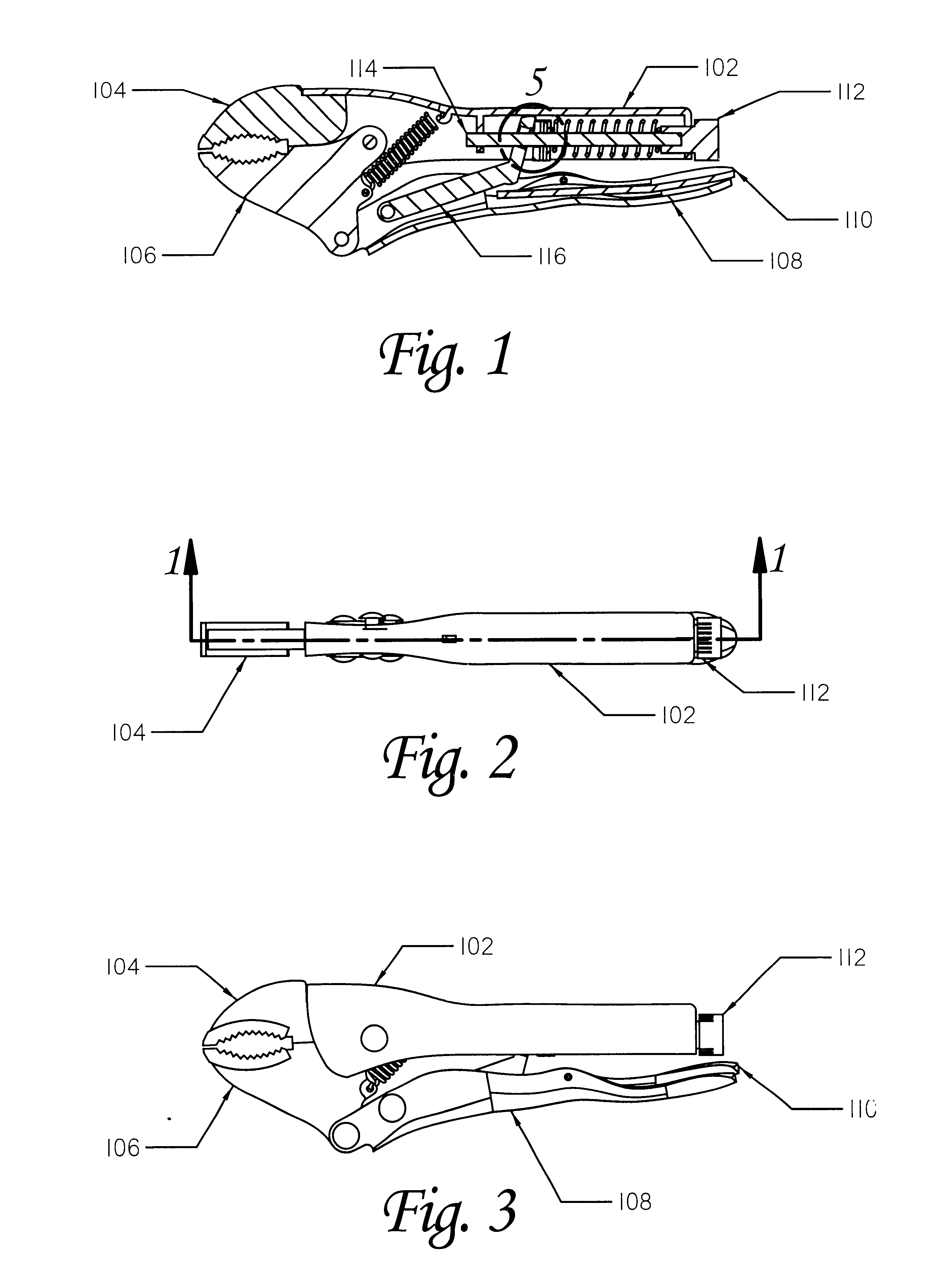
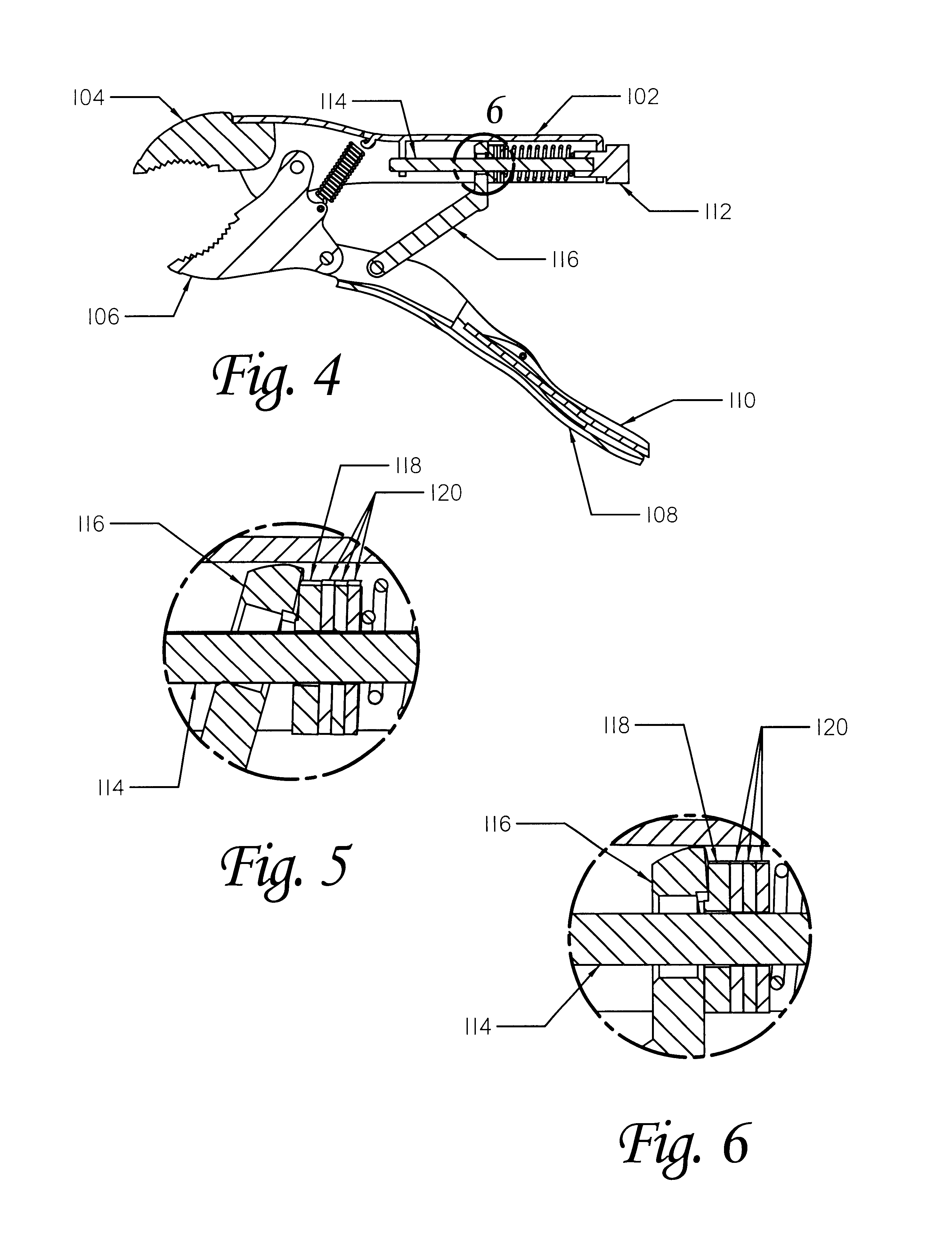
The present invention is a self adjusting, variable grip strength closure mechanism for a locking plier or similar tool. It is described herein primarily with reference to an otherwise conventional locking plier. Much of that part of the structure of the plier which is not associated with the self adjusting or variable grip strength functions is much the same as that of a conventional locking plier. The frame, 102, serves as the fixed portion of the grips and is solidly attached to the fixed jaw, 104. The movable jaw, 106, is rotatably coupled to the frame and moves between open and closed positions relative to the fixed jaw. The handle, 108, moves inward and outward to close and open the plier respectively. It is rotatably coupled to the movable jaw and the push link, 116. When the push link locks to the D-rod (discussed below) the handl...


PUM


Abstract

A self adjusting closure mechanism for a locking plier or similar device. Central to the invention is a set of one or more friction pawls which slide along a support rod, moved by a push link working against a spring. The push link is free to rotate between two positions relative to the rod as it slides. In the first position, and in between the positions, the push link bears against the center of the friction pawls and they remain free to slide along the rod. When the push link rotates to the second position, it presses on the edge of the pawls, causing them to tilt, coupling to the rod and preventing movement along the rod. In a typical locking plier, the support rod is mounted to the frame and the opposite end of the push link connects to the handle. As the handle closes, the push link rotates towards its second position and optionally slides along the support rod. When the friction pawls lock, the plier begins to grip and lock on to the work piece. An adjustment mechanism, preferably in the form of a circular ramp interposed between the push link and the pawls, varies the relative angle of the push link where contact is made with the pawls, providing a method of adjusting the grip force of the plier. Preferably this ramp rotates along with the support rod so that turning the rod, by means of a readily accessible knob, alters the grip force of the plier. The starting position of the push link may also be adjustable, varying the width of the plier jaws in their normally open position.

Description

Not Applicable1. Field of the inventionThe present invention relates to the field of self adjusting tools and specifically to locking pliers, wrenches, or vises which self adjust to the size of the work piece.2. Background InformationLocking pliers are well known in the industry and are exemplified by the Vise Grip.RTM. line of pliers. This type of tool offers significant advantage over conventional pliers in that it can be locked on to a work piece by squeezing the handles together until they over-center slightly, locking in position, the plier and work piece can then be manipulated without exerting any additional effort to keep the pliers closed. An adjustment screw adjusts the plier to fit a range of work piece sizes.One major disadvantage to known locking pliers it that the adjusting screw, while effective, is slow to manipulate. The full range of adjustment may be as much as one inch or more and requires many turns of the adjusting screw to accomplish. The time required to perf...

Claims


Application Information

Patent Timeline
Patent Type & Authority Patents(United States)
IPC IPC(8): B25B13/00B25B13/12B25B13/50B25B7/12B25B7/00
CPCB25B7/123B25B13/5058B25B13/12Y10T74/2066
Inventor KESINGER, DONALD A.KESINGER, ERIC S.
Owner BLACK & DECKER INC
Learn More