
Multicontact electrical connector and rotating electrical machine bearing same

a technology of multi-contact electrical connectors and bearings, which is applied in the direction of coupling contact members, coupling device connections, electric discharge lamps, etc., can solve the problems of increasing the risk of corrosion and deterioration of electrical contacts, and entail a substantial cost, and achieves the effect of simple first sub-assembly and great reliability

Inactive Publication Date: 2004-02-17
VALEO EQUIP ELECTRIC MOTEUR
View PDF7 Cites 21 Cited by
  • Summary
  • Abstract
  • Description
  • Claims
  • Application Information

AI Technical Summary

Benefits of technology

The object of the present invention is to simplify the first subassembly of the connector while having a connector of great reliability.
The box is advantageously ribbed in order to increase its strength, and the same goes for the cover, which advantageously features means for preventing the first conducting elements rising up. Thus the bending of the first electrically conducting elements is controlled.

Problems solved by technology

On one hand, it is necessary to form as many fixings as there are electrical connections to be formed, which entails a substantial cost given that the number of pieces, as well as the fitting times are multiplied by the number of connections to be formed.
Moreover, the contacts are formed by simple pressure between the conducting regions of the device and of the cable and they are then subjected to vibration as well as to external conditions which increases the risk of corrosion and of deterioration of the electrical contact.

Method used


Image

  • Multicontact electrical connector and rotating electrical machine bearing same
  • Multicontact electrical connector and rotating electrical machine bearing same
  • Multicontact electrical connector and rotating electrical machine bearing same

Examples


Embodiment Construction

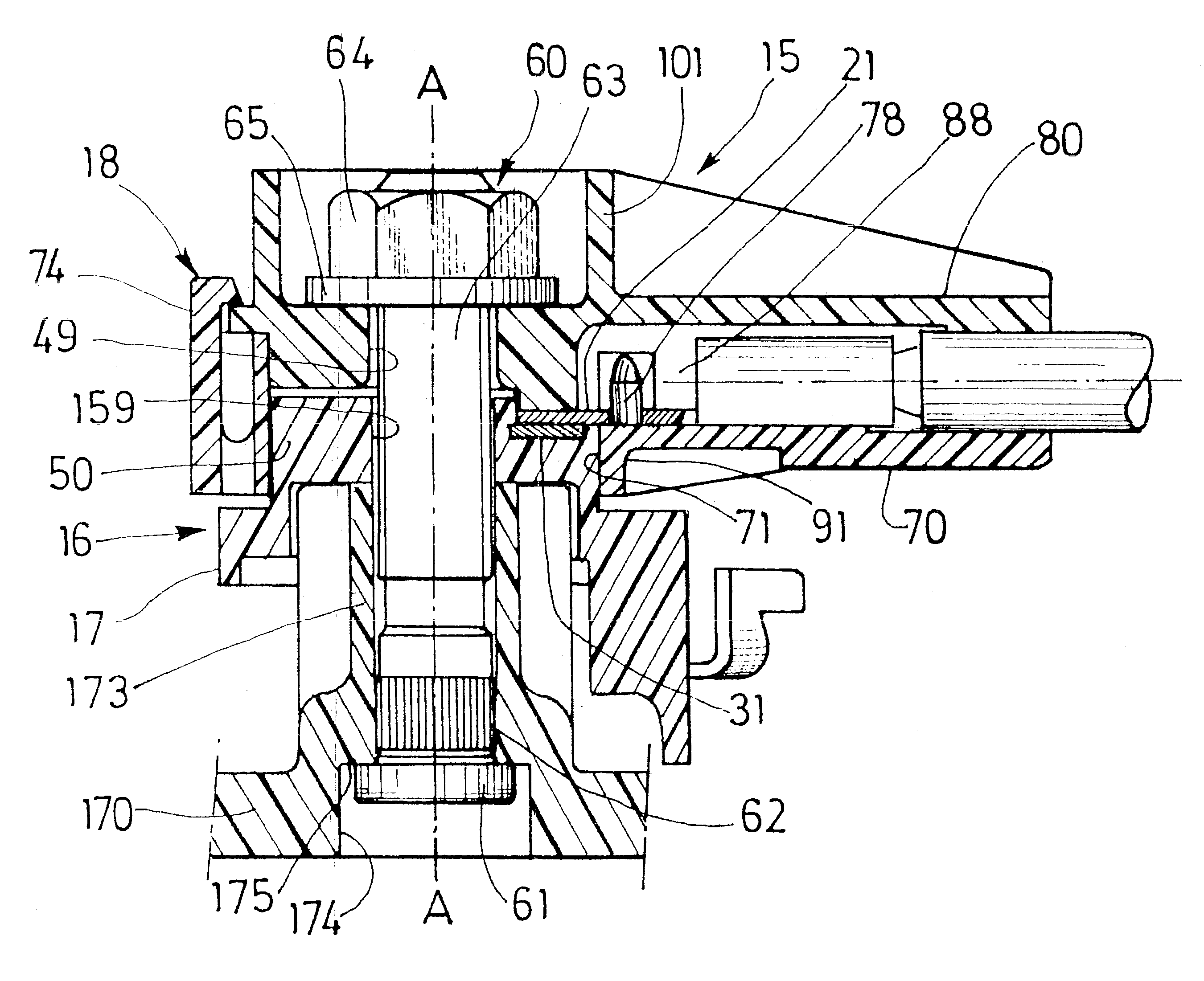
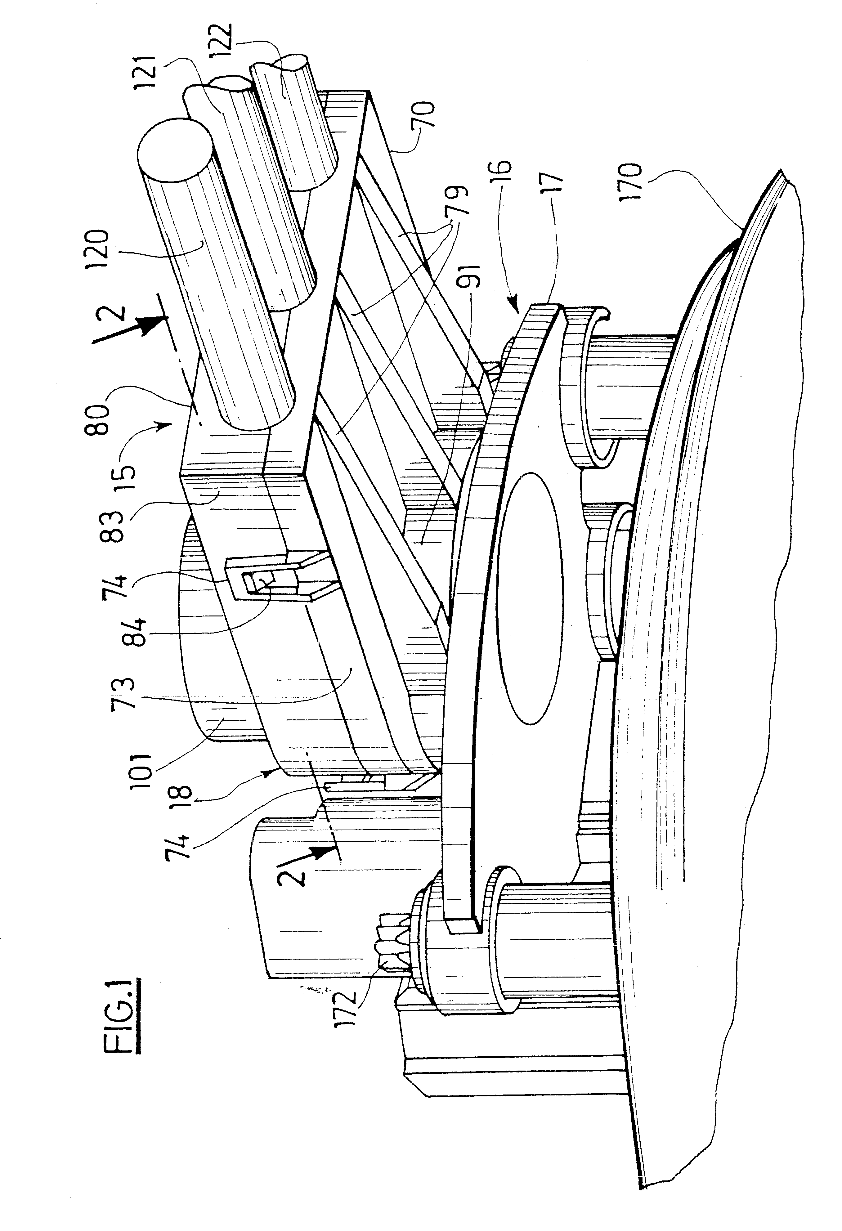
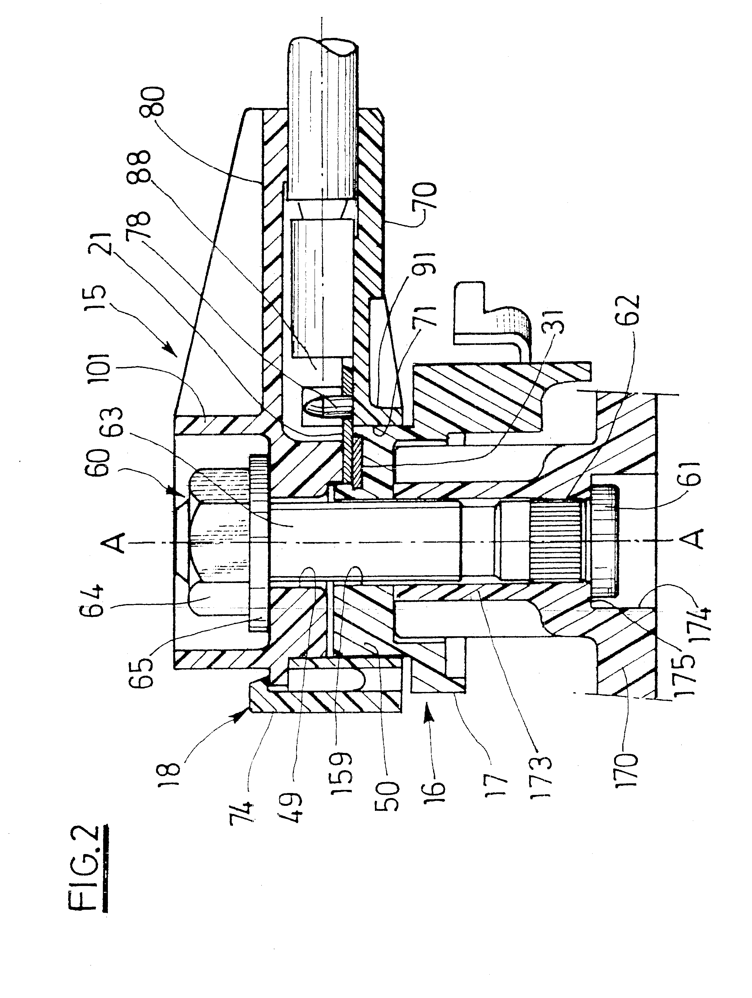
In the description, an orientation from front to rear and upper and lower will be used; this corresponds to the orientation from left to right and top and bottom in accordance with FIGS. 1 and 2.

A connector according to the invention has been represented in the figures, consisting of a first, upper subassembly 15 linked to electrical cables 120, 121, 122, and of a second, lower subassembly 16 linked to the armature of a rotating electric machine, for example to the stator of a motor-vehicle alternator, which, in a variant, may be reversible and operate in electric-motor mode in order to start the motor vehicle. Such an alternator is called alternator / starter.

Here, the connector is mounted on the rear bearing 170 of an alternator / starter, as described in the document FR-00 03131 filed on Mar. 10, 2000 and published under number FR-A-2 806 223 to which reference should be made for further details.

This rear bearing 170 carries, fixedly, a brush holder 171, the brushes of which have not...


PUM


Abstract

Connector for forming an electrical connection between, on the one hand, a first subassembly (15) comprising at least two first electrically conducting elements and, on the other hand, a second subassembly (16) comprising at least two second electrically conducting elements, in which assembling means (60) act between the pressure area and the reaction area so as to clamp between them first and second bearing surfaces and in which the first subassembly (15) includes a casing (18) for positioning and flexible mounting of the first elements; the said casing carrying the pressure area and, opposite the pressure area, including an orifice (71) for allowing movement of the first bearing surfaces.

Description

The invention relates to an electrical connector with multiple contacts and a rotating electrical machine bearing such a connector.The invention relates more particularly to a connector for forming an electrical connection between two subassemblies, the said connector belonging to a connecting device including electrical cables linking together the two connectors each associated with the subassemblies. Such a connector is described in the document FR-A-2 754 650.Certain devices such as electric motors or electrical generators, for example alternators or alternators / starters, have to be linked electrically to a second device such as a control system mounted in a box called electronics box. Each phase of one of the devices has to be linked to the corresponding phase of the other device. This link can be achieved by direct contact between the corresponding phases of the two devices but, in the general way, it is formed by cables comprising several electrical wires each of which makes i...

Claims


Application Information

Patent Timeline
Patent Type & Authority Patents(United States)
IPC IPC(8): H01R13/621H02K5/22H01R13/502H01R13/506H02K5/14H01R39/00H01R39/38H02K11/04H01R4/38
CPCH01R13/506H01R13/621H02K5/225H02K11/048H01R39/38H02K5/141H02K11/046H02K11/05H02K5/22
Inventor ABADIA, ROGERMASRIERA, SERGE
Owner VALEO EQUIP ELECTRIC MOTEUR
Learn More