Sunroof device

a sunroof and sunroof technology, applied in the direction of roofs, mechanical devices, transportation and packaging, etc., can solve the problems of deformation of the guide rail and damage to the rail

Inactive Publication Date: 2003-11-11
AISIN SEIKI KK
View PDF25 Cites 21 Cited by
  • Summary
  • Abstract
  • Description
  • Claims
  • Application Information

AI Technical Summary

Problems solved by technology

In an occasion of some troubles on the parts of the sunroof, and when the connection has to be released in order to replace the broken parts...

Method used


Image

  • Sunroof device
  • Sunroof device
  • Sunroof device

Examples


Embodiment Construction

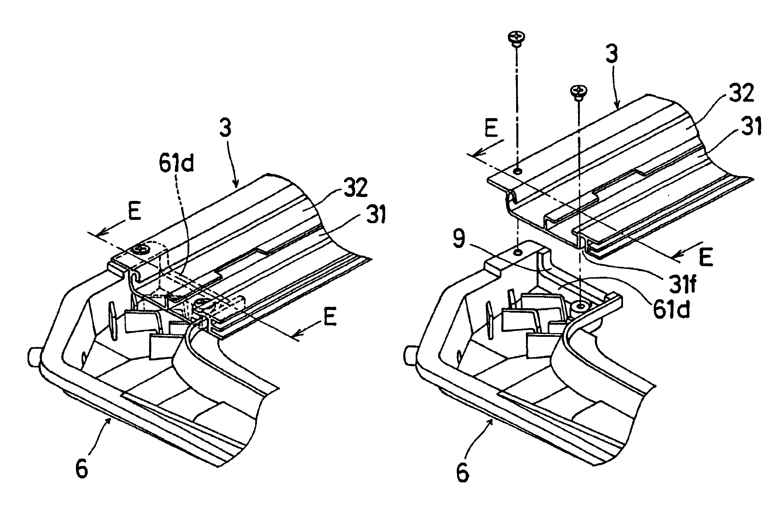
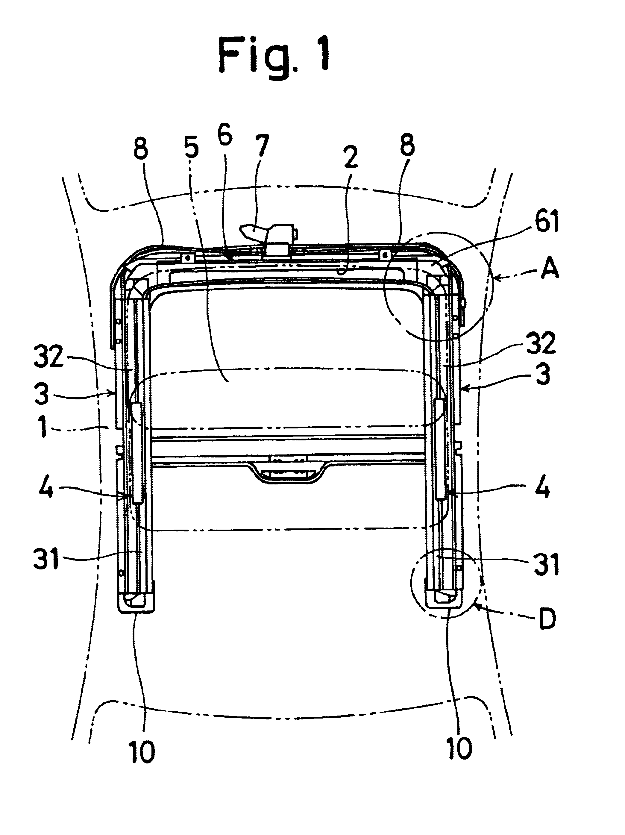
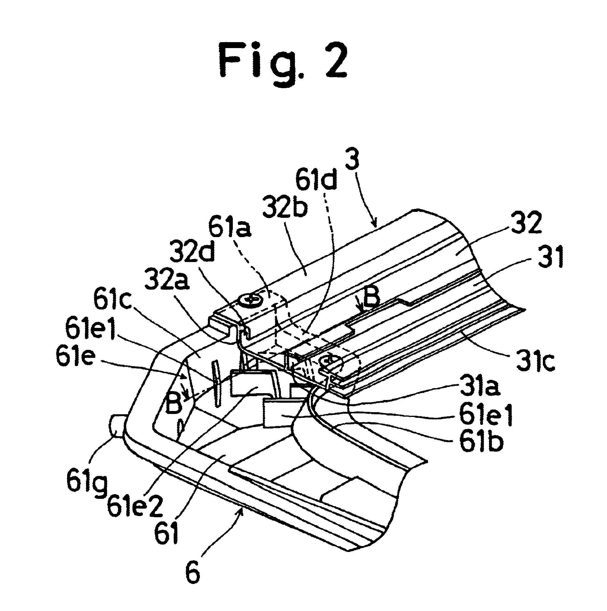
With reference to FIG. 1, a vehicular roof panel 1 comprises an open portion 2. A pair of guide rails 3, 3 (right and left side) extending in a vehicular longitudinal direction, which is in coincidence with the vertical direction in FIG. 1, are arranged along a pair of opposed inner peripheries of the open portion 2 respectively, and are secured thereto. A slide panel 5 is secured, by way of well-known link mechanism (not shown), to each of the guide rails 3, 3 slidably in the vehicular longitudinal direction. At a front periphery of the open portion, there is provided a front frame 6 to which each of the guide rails 3, 3 is connected by connecting mechanism as will be detailed later. In addition, a well-known driving mechanism 7 is fixed to the front frame 6 and is operatively connected to each link mechanism by cables (not shown). The cables are geared cables which are slidably fitted in pipes 8 and the guide rails 3, 3.

In the foregoing structure, when the driving mechanism 7 is d...


PUM


Abstract

A sunroof device is made up of a pair of guide rails placed at laterally opposed inner peripheries of an open area of a vehicle. The pair of guide rails support a movable panel covering and uncovering the open area. A first gutter portion extends along a lengthwise direction of the guide rail. A second gutter portion is positioned below the first gutter portion and is brought into fluid communication with an end of the first gutter portion, characterized in that the second gutter portion is formed with an upstanding wall located at a distance from the end of the first gutter portion when the second gutter portion is brought into an overlap condition in such a manner that the upstanding wall defines an area of the second gutter portion to be overlapped with the first gutter portion. An easy connection can be made between the first gutter portion and the second gutter portion.

Description

1. Field of the InventionThe present invention is directed to a vehicular sunroof device wherein a guide rail and a front frame are constructed in separate fashion and the guide rail is also provided with a gutter portion.2. Prior ArtOne of the conventional or prior art sunroof devices of the type is disclosed in, for example, Japanese Unexamined Patent Publication (so-called "KOKAI KOHOH") No. H06-336119. This conventional or prior art sunroof device is made up of a pair of guide rails provided on a pair of inner peripheries of an open portion formed in a vehicular roof panel. Each of the guide rails includes a first gutter portion and a guide portion which is formed integrally with the first gutter portion, and supports a movable panel which covers and uncovers the open portion of the vehicular roof panel. A front frame placed on a front peripheral portion of the open portion of the vehicular roof panel, connected to both of the guide rails has a second gutter portion which is in ...

Claims


Application Information

Patent Timeline
IPC IPC(8): B60J7/02B60R13/00B60R13/07B60J10/82
CPCB60R13/07B60J7/022B60J7/0084
Inventor NAGASHIMA, YOUJIMAKINO, HIROSHIMAETA, KENJIOCHIAI, HIRONORI
Owner AISIN SEIKI KK
Why Eureka
Try Eureka