
Method of forming enlarged pile heads

a technology of enlarged piles and pile heads, which is applied in the direction of bulkheads/piles, caissons, constructions, etc., can solve the problems of weakening the load bearing capacity of the pile, breaking the top of the installed pile, etc., and achieves the effect of facilitating the radial flow of material and supplying strength and load bearing capacity

Inactive Publication Date: 2003-11-04
KVAERNER CEMENTATION FOUND LTD
View PDF10 Cites 4 Cited by
  • Summary
  • Abstract
  • Description
  • Claims
  • Application Information

AI Technical Summary

Benefits of technology

Preferably, the enlarged head forming tool has a substantially central aperture. This allows a drive dolly to be positioned in the enlarged head forming tool to facilitate the penetration of the tool into the ground. Preferably the tool is driven into the ground by means of a percussive force being applied to the top of the drive dolly by means of a hammer. Alternatively, the enlarged head forming tool may be driven into the ground by means of rotation. This may be facilitated by means of an auger which is releasably fitted to the tool.
Once the pile has been driven into the ground, and the enlarged head former has been removed, the pre-cast pile is broken down to a predetermined level below the ground. Preferably, the pile is broken down to between 100 mm and 150 mm below the ground. A reinforcement cage may also be placed within the void above the trimmed pre-cast pile before the void is filled with concrete or grout. The reinforcement cage advantageously serves to supplement the strength and load bearing capacity of the enlarged diameter pile head.
A number of configurations are envisaged for the enlarged pile head forming tool including those of circular, square or hexagonal cross section. The tool may comprise a collar device having a longitudinal section with two substantially parallel sides and a tapered section. Alternatively, the tool may comprise a first cylindrical section of greater diameter, a second cylindrical section having a smaller diameter and a tapered section extending between said first and second cylindrical sections. Furthermore, the outer surface of the tool may be provided with one or a number of blades which can be advantageously arranged to facilitate the radial flow of material in an outward direction as the tool penetrates the ground.

Problems solved by technology

This method however suffers from the disadvantage that it is often necessary for the top of the installed pile to be broken as the head volume is excavated.
This can cause discontinuities or cracks to occur in the pile shaft, which will inevitably weaken the load bearing capacity of the pile.

Method used


Image

  • Method of forming enlarged pile heads
  • Method of forming enlarged pile heads
  • Method of forming enlarged pile heads

Examples


Embodiment Construction

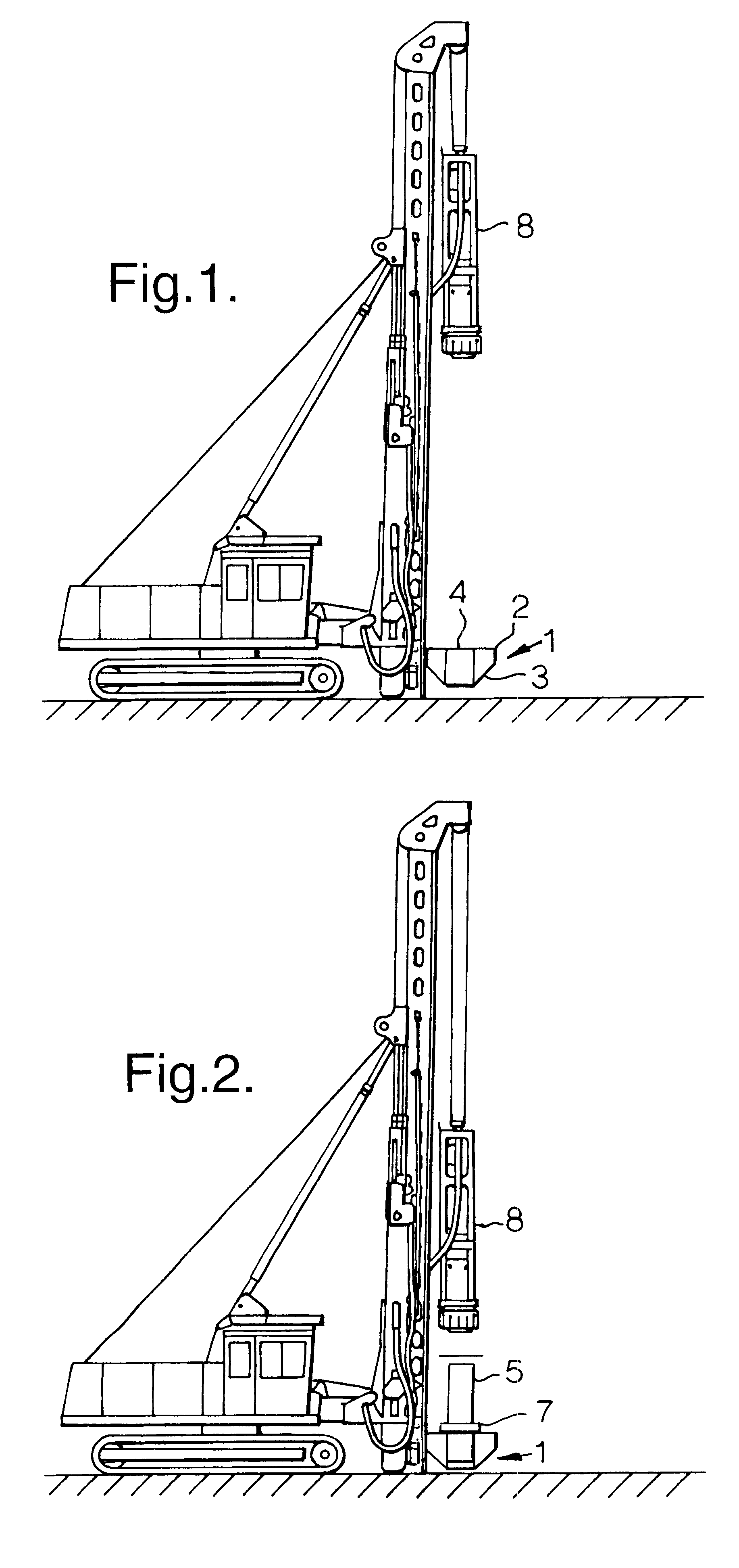
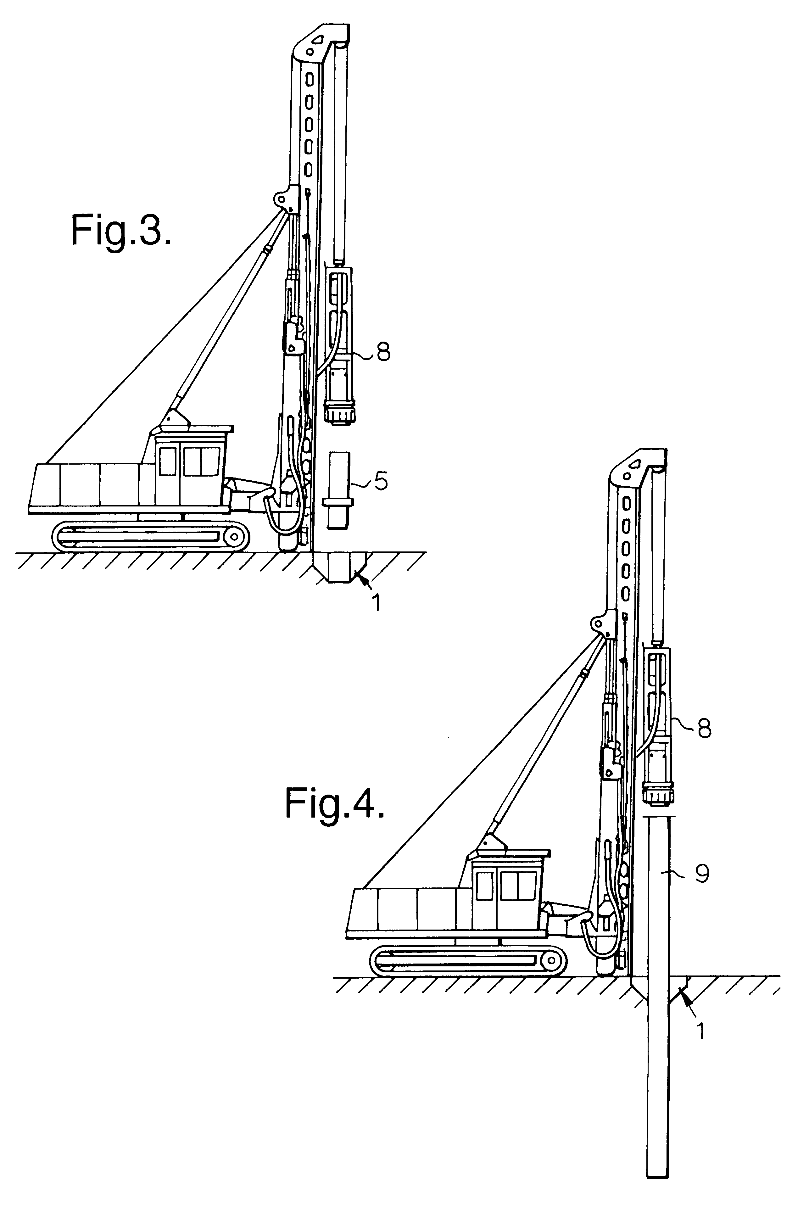
FIG. 1 shows an enlarged head forming tool 1 positioned over the required pile position on the ground. The enlarged head forming tool comprises a cylindrical section 2 and a tapered section 3. A central aperture 4 extends through the device into which a drive dolly 5 may be positioned. The lower end of the drive dolly is accommodated within the central aperture of the enlarged head former. The drive dolly is provided with a circumferential rim 7 which has a greater diameter than the diameter of the central aperture 4. This enables the percussive force applied to the drive dolly by means of a hammer 8, to be transmitted to the enlarged head forming tool, as shown in FIG. 2.

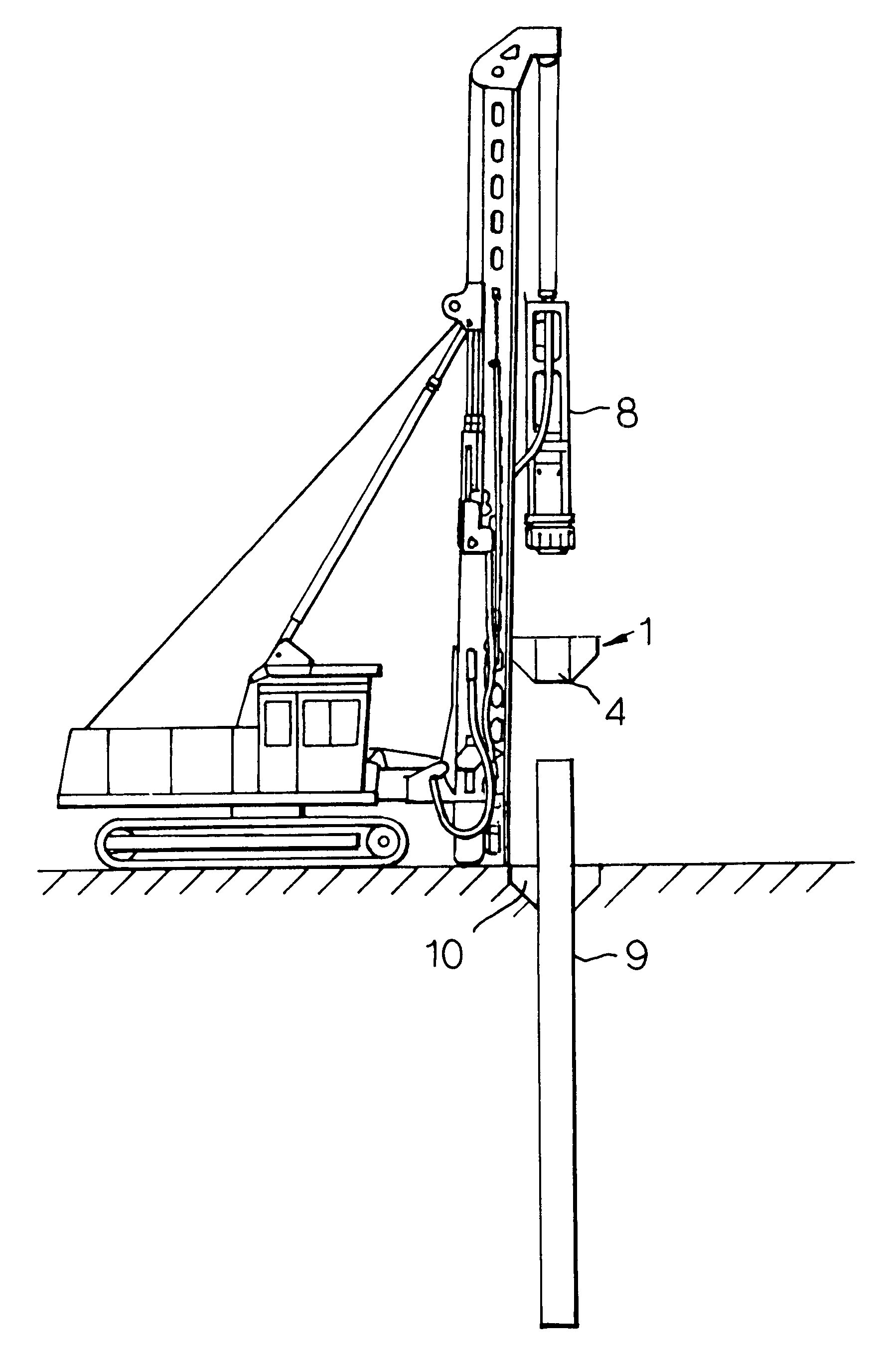
Once the enlarged head forming tool has reached a predetermined depth, the hammer 8 is lifted and the drive dolly 5 is raised and removed as shown in FIG. 3. FIG. 4 shows the installation of a pre-cast pile 9 in the ground. The hammer 8 is suspended by a winch and exerts a series of percussive blows on the top of t...


PUM


Abstract

The present application relates to a method of installing a pre-cast pile in the ground which involves applying an enlarged head forming tool to the ground until a volume of soil has been displaced or removed so as to form a void at the surface of the ground. The pre-cast pile is then driven into the ground to a predetermined depth below the void and the void is then filled with concrete or grout to form a cast-in-situ pile head. The diameter of the pile head is greater than the diameter of the pile shaft.

Description

1. Technical Field of the InventionThe present invention relates to a method of installing a pre-cast pile in the ground, the method involving the construction of an enlarged diameter pile head.2. Prior ArtPiles are used in the construction industry to provide foundation support for buildings and the like. Two common piling techniques involve the use of cast-in-situ piles and pre-cast piles. Cast-in-situ methods involve the use of an auger to penetrate the ground to a certain depth so as to form an underground void. Concrete is then pumped into the underground void left by the auger so as to form an underground column. In driven piling operations, a pre-cast concrete pile is driven into the ground, usually by means of successive percussive forces applied to the head of the pile, until a predetermined depth is reached. The top of the pile column may need to be trimmed to a level at, or just below, the ground.It is advantageous in some applications for the top, or head, of a foundatio...

Claims


Application Information

Patent Timeline
Patent Type & Authority Patents(United States)
IPC IPC(8): E02D27/16E02D27/12E02D5/24E02D5/30
CPCE02D27/16E02D5/30
Inventor BARTLETT, GRAHAMENGLAND, MELVIN GERRARD
Owner KVAERNER CEMENTATION FOUND LTD
Learn More