
Electric marine propulsion employing switched reluctance motor drive

a technology of switched reluctance and motor drive, which is applied in the direction of marine propulsion, electric devices, and vessel construction, etc., can solve the problems of electric noise, unfavorable motor performance, and inevitable wear of brushes, and achieves the effect of reducing the noise of brushes

Inactive Publication Date: 2003-10-28
BRP US
View PDF11 Cites 15 Cited by
  • Summary
  • Abstract
  • Description
  • Claims
  • Application Information

AI Technical Summary

Problems solved by technology

For example, commutated motors require frictional contact between the commutator and brushes, resulting in mechanical and electrical noise.
The inevitable wear of the brushes produces particulates which are detrimental to the motor's performance, such as contamination and degradation of the bearings.
Furthermore, because the electrical windings are located away from the housing, and because the majority of heat is generated by the windings, heat transfer is inefficient.
All of these factors lead to inefficiencies and / or shortening of the useful life of the motor.
However, these systems too have suffered from relatively low efficiencies, resulting in high energy consumption, excessive heating, and the need to oversize the motors to obtain the desired output thrust.

Method used


Image

  • Electric marine propulsion employing switched reluctance motor drive
  • Electric marine propulsion employing switched reluctance motor drive
  • Electric marine propulsion employing switched reluctance motor drive

Examples


Embodiment Construction

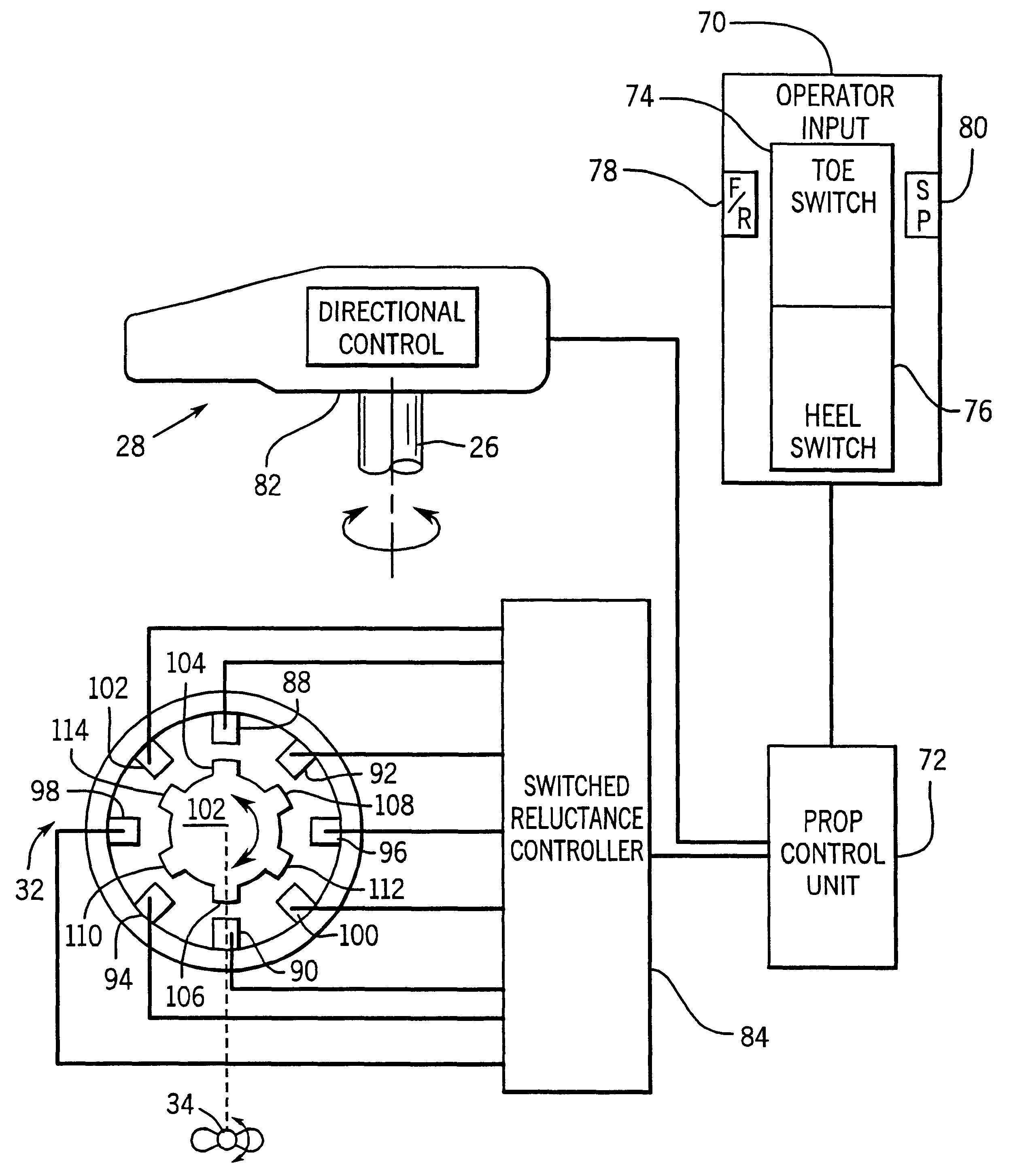
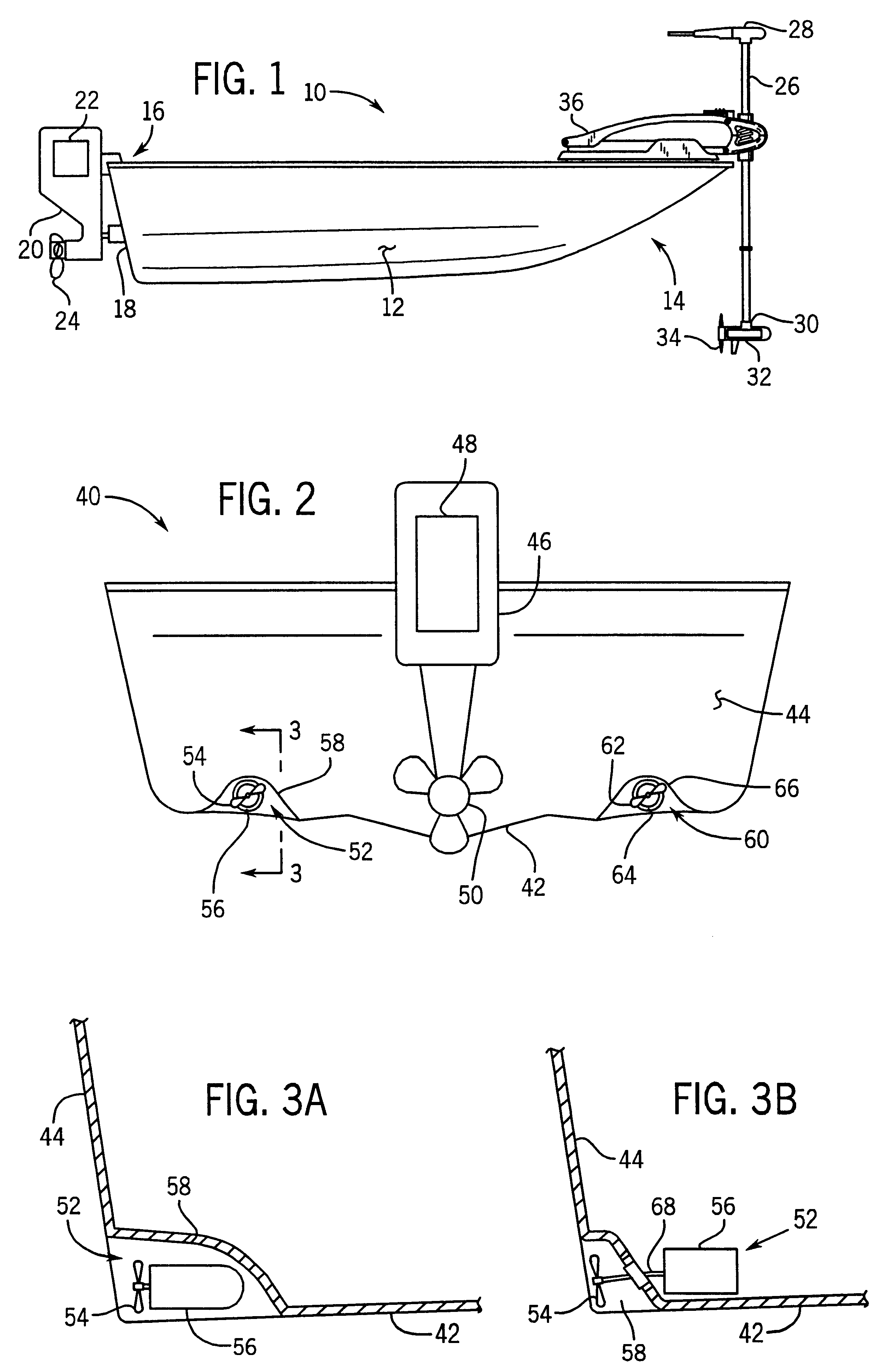
Turning now to the drawings and referring first to FIG. 1, a watercraft 10 is shown. The watercraft 10 includes a hull 12 which has a bow section 14 and a stern section 16. The stem section includes a transom 18. Mounted to the transom 18 is a primary propulsion unit 20 shown here as an outboard motor. The primary propulsion system includes an internal combustion engine 22, which is drivingly coupled to a prop 24. The prop 24 is driven by the internal combustion engine 22 such that the prop 24 produces a thrust when rotated below the waterline of the craft. It is noted that the primary propulsion system 20 need not comprise an outboard motor. Rather, it is contemplated that other primary propulsion systems may be used such as an inboard or inboard / outboard configuration. Such a configuration typically places the internal combustion engine inside the hull 12 of the watercraft 10 rather than on the exterior of the transom 18.

At the bow 14 of the watercraft 10 is a secondary propulsion...


PUM


Abstract

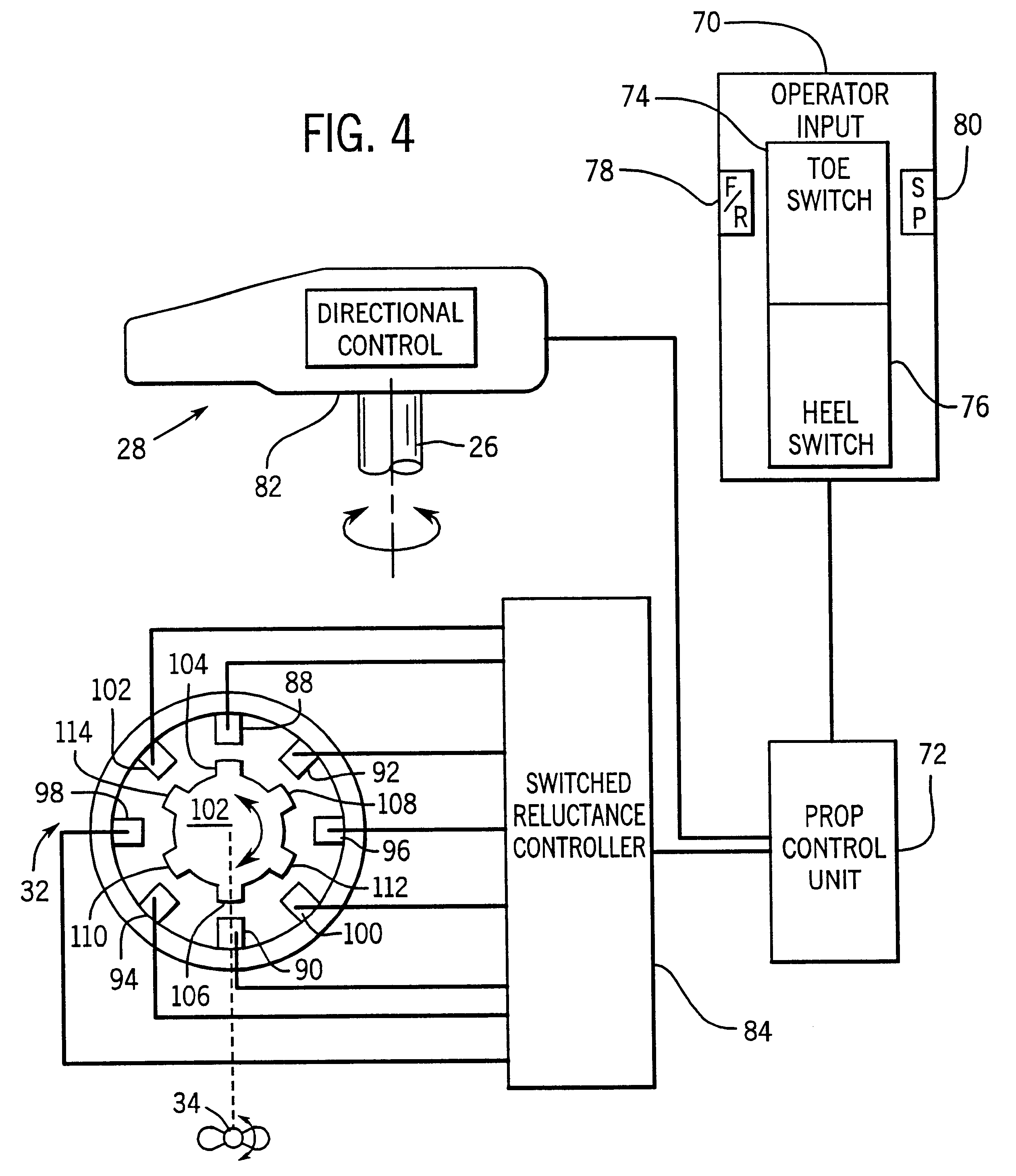
A propulsion unit for a watercraft including a prop which is adapted for producing thrust when rotated, and an electric motor drivingly coupled to the prop. The electric motor is of the switched reluctance type which includes a stator, formed of a plurality of windings, and a rotor having a plurality of poles about the circumference of the rotor. The stator windings are divided into a plurality of phases which are sequentially energized by electric current. A controller is coupled to the electric motor to determine the order and timing of phase energization. Proper sequencing of the phase energization creates a dynamic magnetic field inducing the rotor to rotate accordingly.

Description

1. Field of the InventionThe present invention relates generally to electric propulsion units for recreational watercraft. More specifically the present invention relates to propulsion units which employ brushless DC motors and more particularly the utilization of switched reluctance motors in such propulsion units.2. Description of the Related ArtRecreational watercraft are extremely popular for a variety of uses. Some of the more typical uses may include water skiing, other suitable towing activities, fishing, and pleasure riding, just to name a few. All of these activities typically require the ability of a propulsion system to move the watercraft through the water by providing an adequate amount of thrust.Many watercraft rely on an outboard, or inboard / outboard motor as a primary propulsion device. Such motors generally include an internal combustion engine to supply the required thrust. In watercraft outfitted for fishing purposes, a secondary propulsion system is often employe...

Claims


Application Information

Patent Timeline
IPC IPC(8): B60L11/00B63H23/24B63H23/00H02P25/08H02P25/02
CPCB60L11/00H02P25/082B63H23/24B60L2220/18Y02T10/642B60L50/00H02P25/0925Y02T10/64
Inventor GRIFFITH, SR., THOMAS E.
Owner BRP US
Learn More