Process for the installation and tensioning of a brace having a false bearing, in particular a stay cable for a cable-stayed bridge and anchoring device with which to carry out the process

a technology of false bearings and tensioning devices, which is applied in the direction of turning machine accessories, snap fasteners, drawing profiling tools, etc., can solve the problems of difficult to determine exactly, the reliability of anchoring may be jeopardized, and the reliability of anti-corrosion protection in this area may be jeopardized, so as to achieve a simple and less costly method

Inactive Publication Date: 2003-10-21
DYWIDAG SYST INT GMBH (DE)
View PDF17 Cites 10 Cited by
  • Summary
  • Abstract
  • Description
  • Claims
  • Application Information

AI Technical Summary

Benefits of technology

Set against this background, the object of the invention is to find a simpler and less costly method of removing the PE jacket in the area of the tensioned end or of exposing the strand in this area in such a manner that, in its final state, the remaining PE jacket ends as close as possible to the area in which the strand is anchored.

Problems solved by technology

Here it is often difficult to determine exactly prior to installation the length along which the PE jacket must be removed in order to anchor the strands properly.
If the exposed length proves to be too short, the reliability of the anchoring may be jeopardized.
If on the other hand the exposed area is too long, the reliability of the anti-corrosion protection in this area may be jeopardized.
However, the jacket-removing tool required to carry out this process is costly.

Method used


Image

  • Process for the installation and tensioning of a brace having a false bearing, in particular a stay cable for a cable-stayed bridge and anchoring device with which to carry out the process
  • Process for the installation and tensioning of a brace having a false bearing, in particular a stay cable for a cable-stayed bridge and anchoring device with which to carry out the process
  • Process for the installation and tensioning of a brace having a false bearing, in particular a stay cable for a cable-stayed bridge and anchoring device with which to carry out the process

Examples


Embodiment Construction

As disclosed in the invention this object is achieved by means of the process described in claim 1.

Two independent anchoring devices suitable for carrying out this process for this type of strand are indicated in claims 7 and 8.

Advantageous developments are detailed in the sub-claims.

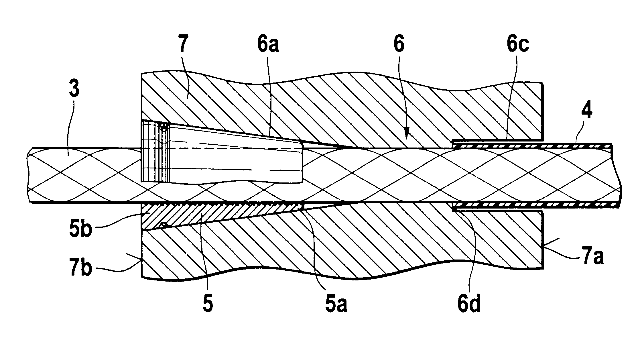
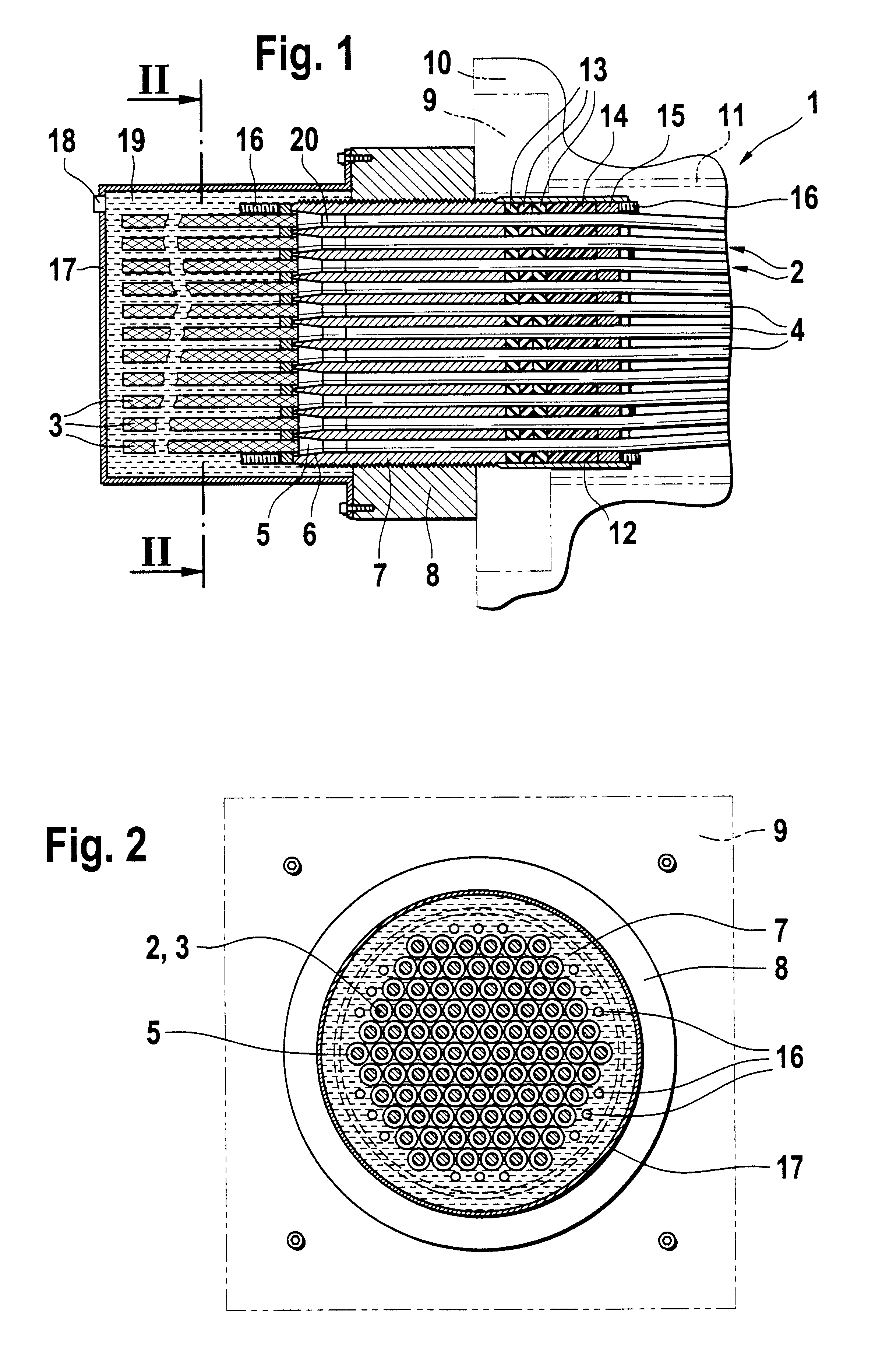
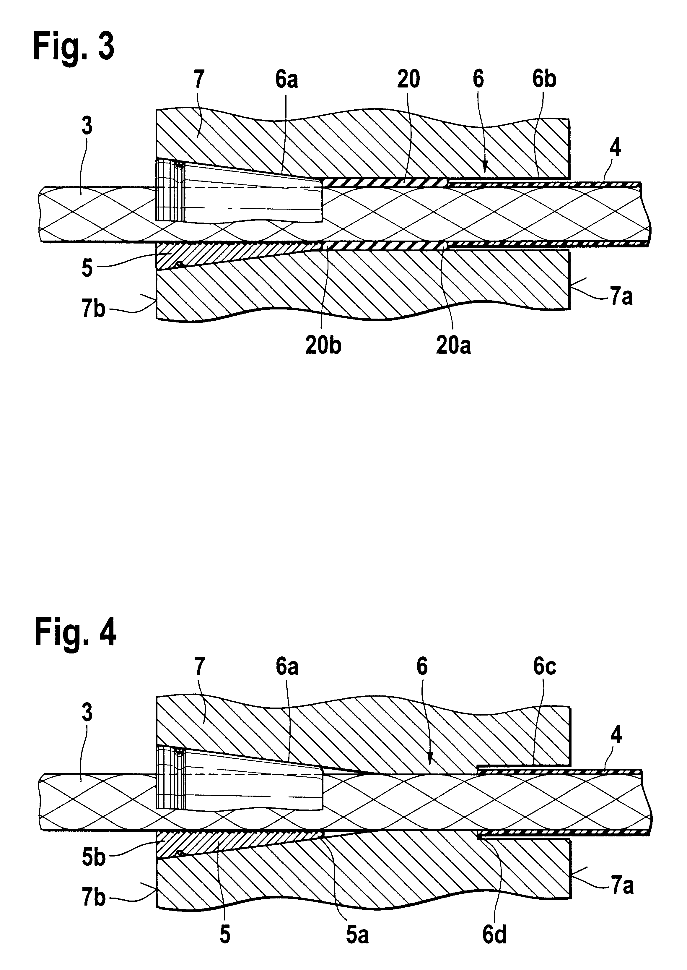
Rather than removing the plastic jacket which fits tightly around the individual elements of a brace at the end at which said individual elements are tensioned and anchored along the entire length of the extension which occurs during tensioning, the basic idea behind the invention is to prevent said jacket from making the longitudinal movement in the anchoring area caused by the tensioning of the individual elements and thereby compressing it in the area prior to anchoring in so far as it follows the longitudinal movement of the strand during tensioning. During this compression the plastic jacket undergoes first elastic and then, at least in part, plastic deformation.

There are several possible methods o...


PUM

PropertyMeasurementUnit
restoring forceaaaaaaaaaa
external longitudinal forceaaaaaaaaaa
tensioning forceaaaaaaaaaa

Abstract

In order to install or tension a brace (1) having a false bearing, for example a stay cable for a cable-stayed bridge, an external tensioning member or similar comprising a bundle of plastic-sheathed individual elements (2) made of steel, for example, wires, strands of wires or similar, the individual elements (2) are exposed in the area of the anchoring in order that they may be anchored at this point in holes (6) in an anchoring plate (7) which is supported by the building structure (9) by means of wedges (5). In order to ensure that when the strand is anchored the remaining plastic jacket (4) ends as close as possible to the anchoring plate (7), it is suggested that the plastic jacket be prevented from making any longitudinal movement during the extension of each individual element (2) which occurs during tensioning by a stop in the form of an annular shoulder (6d) which surrounds the element (2) in the anchoring area, and thereby compressed.

Description

The invention relates to a process for the installation and tensioning of a brace having a false bearing, for example a stay cable for a cable-stayed bridge, an external tensioning member or similar comprising a bundle of plastic-sheathed individual elements made of steel such as, for example, wires, strands of wires or similar, and anchoring devices suitable for carrying out this process.In many cases braces such as those used in the construction industry for anchoring building components, for example as stay cables for cable-stayed bridges, external tensioning members or similar bracing elements, consist of a bundle of individual elements such as steel wires or strands of wires which are positioned together in a tubular sheath in the free area of the brace, passed through the relevant building components and anchored at the end opposite the point of entry therein by means of anchoring devices. These anchoring devices generally consist of an anchoring plate with holes through which...

Claims


Application Information

Patent Timeline
Patent Type & Authority Patents(United States)
IPC IPC(8): E04G21/12E04C5/12E01D11/04E01D11/00E01D19/16
CPCE04C5/122E04G21/12E04G21/121Y10T24/3909Y10T29/49874Y10T29/49863E01D11/00
Inventor NUTZEL, OSWALD
Owner DYWIDAG SYST INT GMBH (DE)
Why Eureka
Try Eureka