
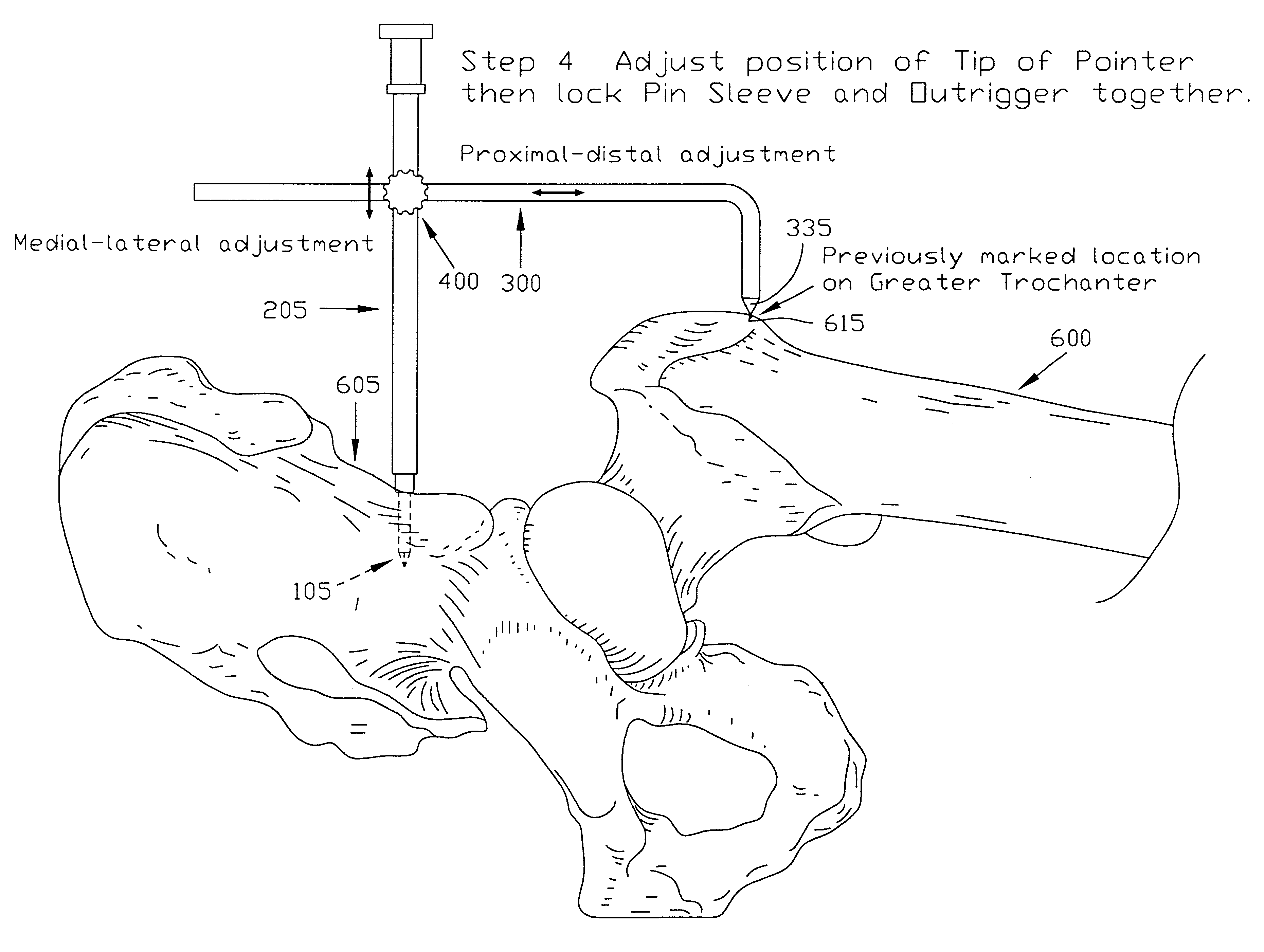
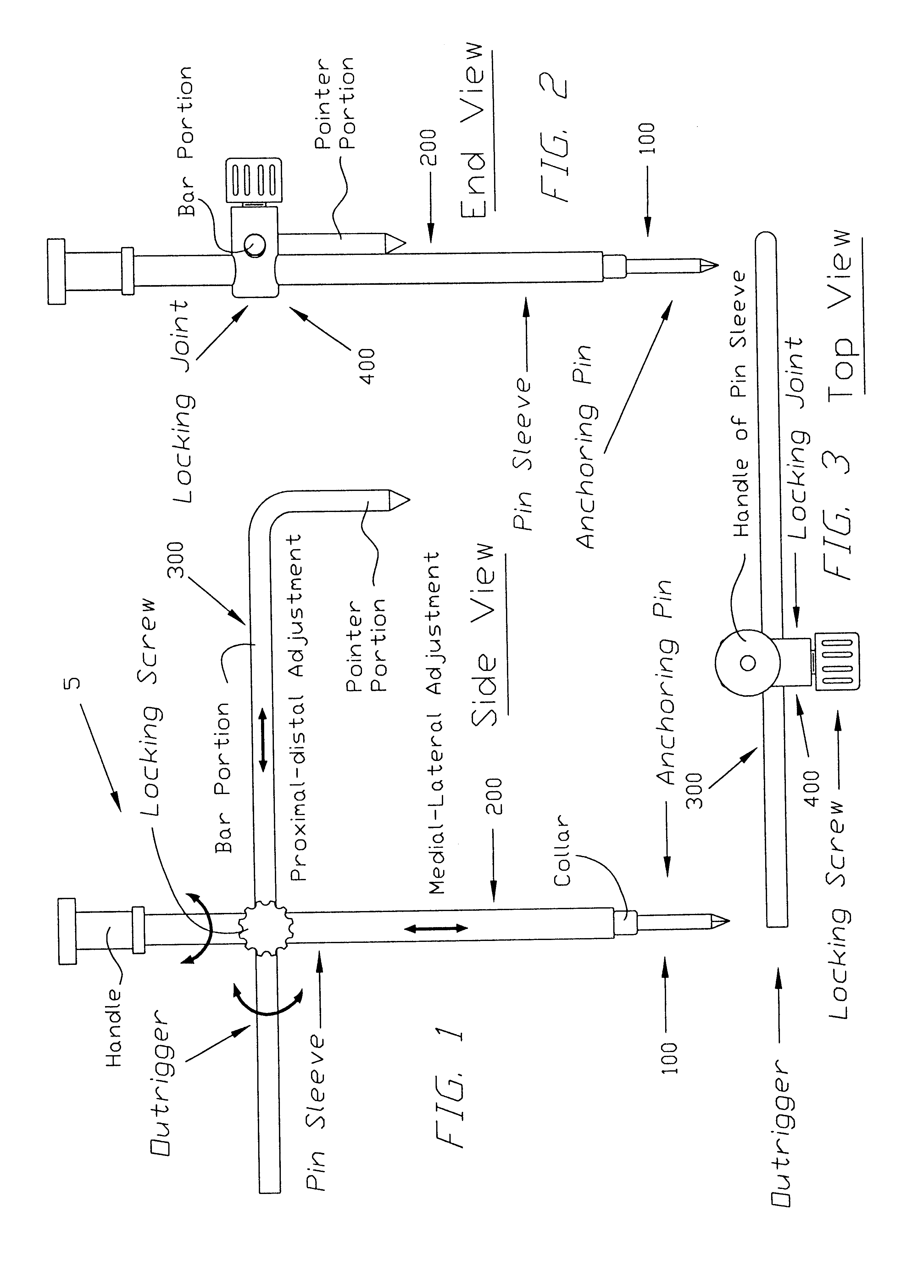
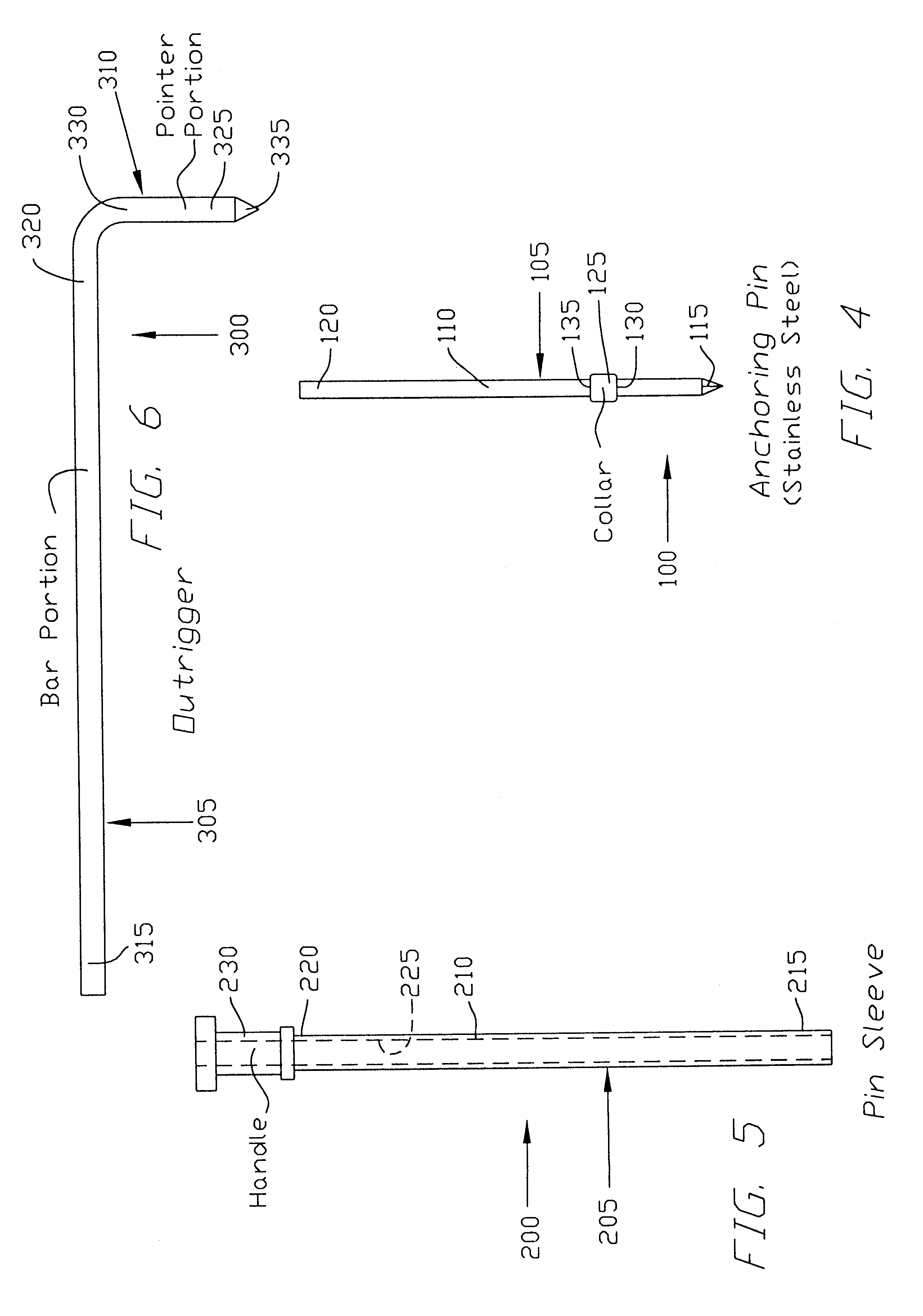
Apparatus and method for determining the relative position of bones during surgery

a technology of relative position and bone position, applied in the field of apparatus and method for determining the relative position of bones during surgery, can solve the problems of unacceptable leg length inequalities, mis-sized lateral offsets, and joint dislocations are possible adverse outcomes of total hip replacement surgeries, and patients who have undergone total hip replacement surgeries are more likely to limp, and the effect of increasing the likelihood of joint dislocations

Inactive Publication Date: 2003-10-14
CHAN KK
View PDF16 Cites 43 Cited by
  • Summary
  • Abstract
  • Description
  • Claims
  • Application Information

AI Technical Summary

Benefits of technology

Enables precise and efficient determination of the relative position of bones, reducing surgical time and minimizing complications such as leg length inequalities and joint dislocations by providing a safe, effective, and easy-to-use apparatus for total hip replacement surgeries.

Problems solved by technology

Unacceptable leg length inequalities, mis-sized lateral offsets, and joint dislocations are possible adverse outcomes of total hip replacement surgeries.
Leg length inequalities and mis-sized lateral offsets (including, particularly, insufficient lateral offsets) can result in a persistent limp for patients who have undergone total hip replacement surgeries.
Also, joint dislocations are more likely to occur if the soft tissue tension across the replaced joint is too lax as a result of a shortened limb and / or an insufficient lateral offset.
Unfortunately, however, all of the existing devices and methods for measuring the position of the femur relative to the ilium tend to suffer from one or more significant disadvantages.
On the one hand, some of the existing devices only measure the longitudinal displacement of the femur, and they do not measure the lateral offset of the femur.
On the other hand, in those devices which can measure both the longitudinal displacement and lateral offset of the femur, the devices tend to be relatively bulky and complicated to install and use.

Method used


Image

  • Apparatus and method for determining the relative position of bones during surgery
  • Apparatus and method for determining the relative position of bones during surgery
  • Apparatus and method for determining the relative position of bones during surgery

Examples


Embodiment Construction

It is, of course, possible to modify the preferred embodiment discussed above without departing from the scope of the present invention.

Thus, for example, outrigger 300 may be replaced by the outrigger 300A shown in FIGS. 20-22. Outrigger 300A comprises a bar portion 305A and a pointer portion 310A. More particularly, bar portion 305A comprises a first end 315A and a second end 320A, and pointer portion 310A comprises a first end 325A and a second end 330A. The second end 320A of bar portion 305A includes a smooth bore 331A (FIG. 22), and a threaded bore 332A (FIG. 22) which intersects bore 331A. Smooth bore 331A is sized to receive pointer portion 310A, and threaded bore 332A is sized to receive a locking screw 333A (FIG. 22), whereby the outrigger's pointer portion 310A may be adjustably positioned relative to the outrigger's bar portion 305A. The first end 325A of pointer portion 310A preferably terminates in a point so as to constitute a pointer 335A.

In use, outrigger 300A is us...


PUM


Abstract

A measuring gauge for measuring the relative position of two bones during surgery, the measuring gauge comprising an anchor, an adapter, an outrigger and a locking joint.< / PTEXT>

Description

This invention relates to surgical apparatus and procedures in general, and more particularly to surgical apparatus and procedures for determining the relative position of bones during surgery, and still more particularly to surgical apparatus and procedures for determining the distal displacement and lateral offset of a patient's femur relative to that patient's ilium during total hip replacement surgery.Unacceptable leg length inequalities, mis-sized lateral offsets, and joint dislocations are possible adverse outcomes of total hip replacement surgeries. Leg length inequalities and mis-sized lateral offsets (including, particularly, insufficient lateral offsets) can result in a persistent limp for patients who have undergone total hip replacement surgeries. Also, joint dislocations are more likely to occur if the soft tissue tension across the replaced joint is too lax as a result of a shortened limb and / or an insufficient lateral offset.It is, therefore, generally desirable to ma...

Claims


Application Information

Patent Timeline
Patent Type & Authority Patents(United States)
IPC IPC(8): A61B17/16A61B17/17A61F2/46A61B19/02A61B19/00A61F2/32A61F2/34A61F2/36
CPCA61B17/175A61F2/4657A61B19/0271A61B2019/0219A61B2019/461A61F2/32A61F2002/4658A61F2002/3611A61F2002/3625A61F2002/3631A61F2/34A61B2050/0065A61B50/33A61B2090/061
Inventor CHAN
Owner CHAN KK
Learn More