Eureka AIR delivers breakthrough ideas for toughest innovation challenges, trusted by R&D personnel around the world.

Efficient and accurate pseudo 2-D inversion scheme for multicomponent induction log data

a multi-component inversion and log data technology, applied in seismology, water-logging instruments, reradiation, etc., can solve the problems of h.sub.xx, h.sub.xx, and suffer from strong borehole and near-zone effects, and corrections cannot completely eliminate near-zone effects

Inactive Publication Date: 2003-09-09
BAKER HUGHES INC
View PDF5 Cites 32 Cited by
  • Summary
  • Abstract
  • Description
  • Claims
  • Application Information

AI Technical Summary

Problems solved by technology

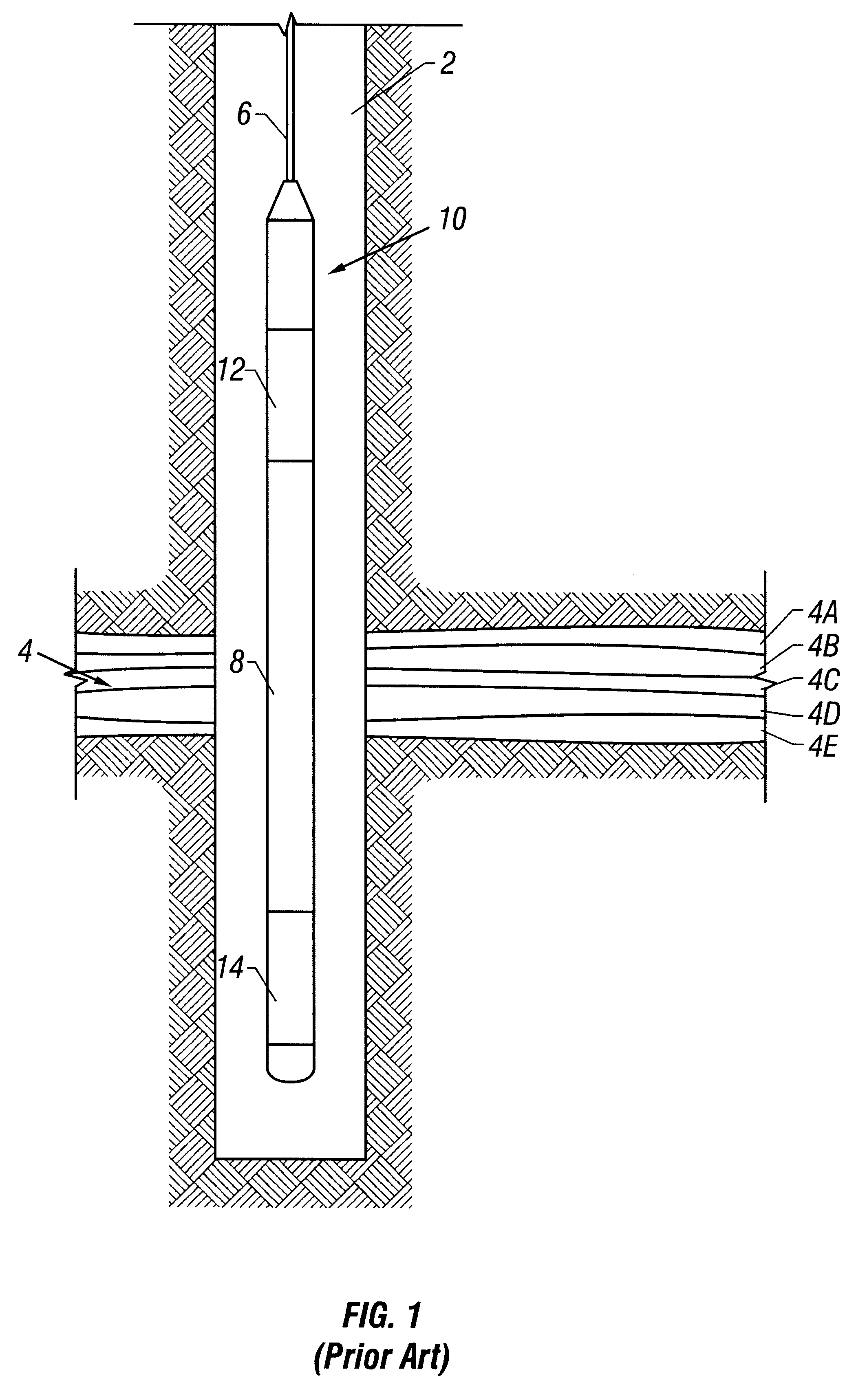
A limitation to the electromagnetic induction resistivity well logging instruments known in the art is that they typically include transmitter coils and receiver coils wound such that the magnetic moments of these coils are substantially parallel only to the axis of the instrument.
However, the new horizontal magnetic field responses, H.sub.xx and H.sub.xx, that are sensitive to the vertical resistivity of the formation can suffer from strong borehole and near-zone effects.
However, in large borehole sizes and conductive mud systems, these corrections cannot completely eliminate the near-zone effects.
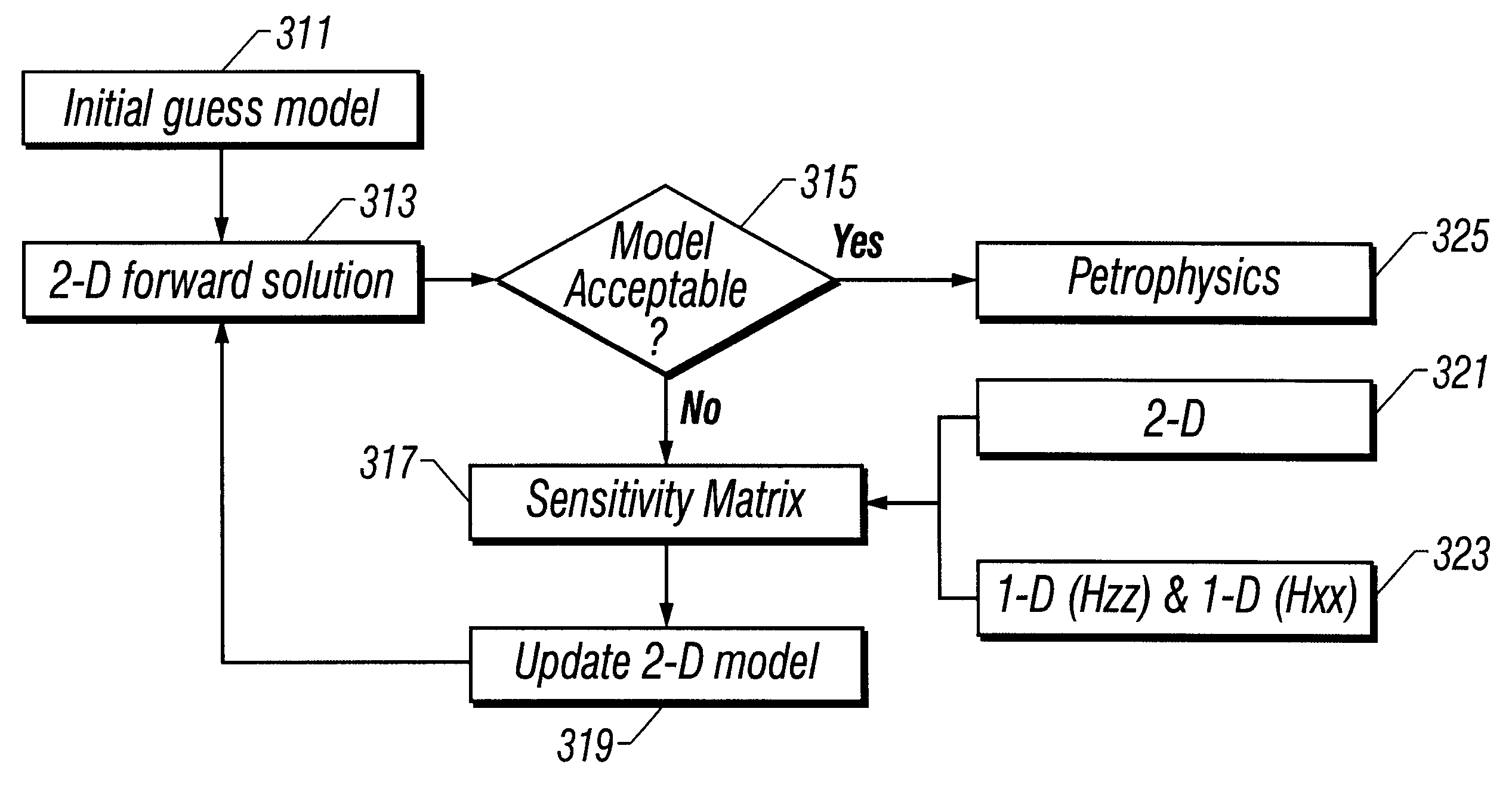
However, a rigorous 2-D inversion is too time-intensive and prohibitive for typical logging applications, because the 2-D forward model response is time consuming and also because inversion schemes typically require the determination of a Jacobian matrix defining the sensitivity of each of the measurements to every one of the parameters in the model.
However, Tabarovsky does not address the problem of inversion of multi-component data.

Method used


Image

  • Efficient and accurate pseudo 2-D inversion scheme for multicomponent induction log data
  • Efficient and accurate pseudo 2-D inversion scheme for multicomponent induction log data
  • Efficient and accurate pseudo 2-D inversion scheme for multicomponent induction log data

Examples


Embodiment Construction

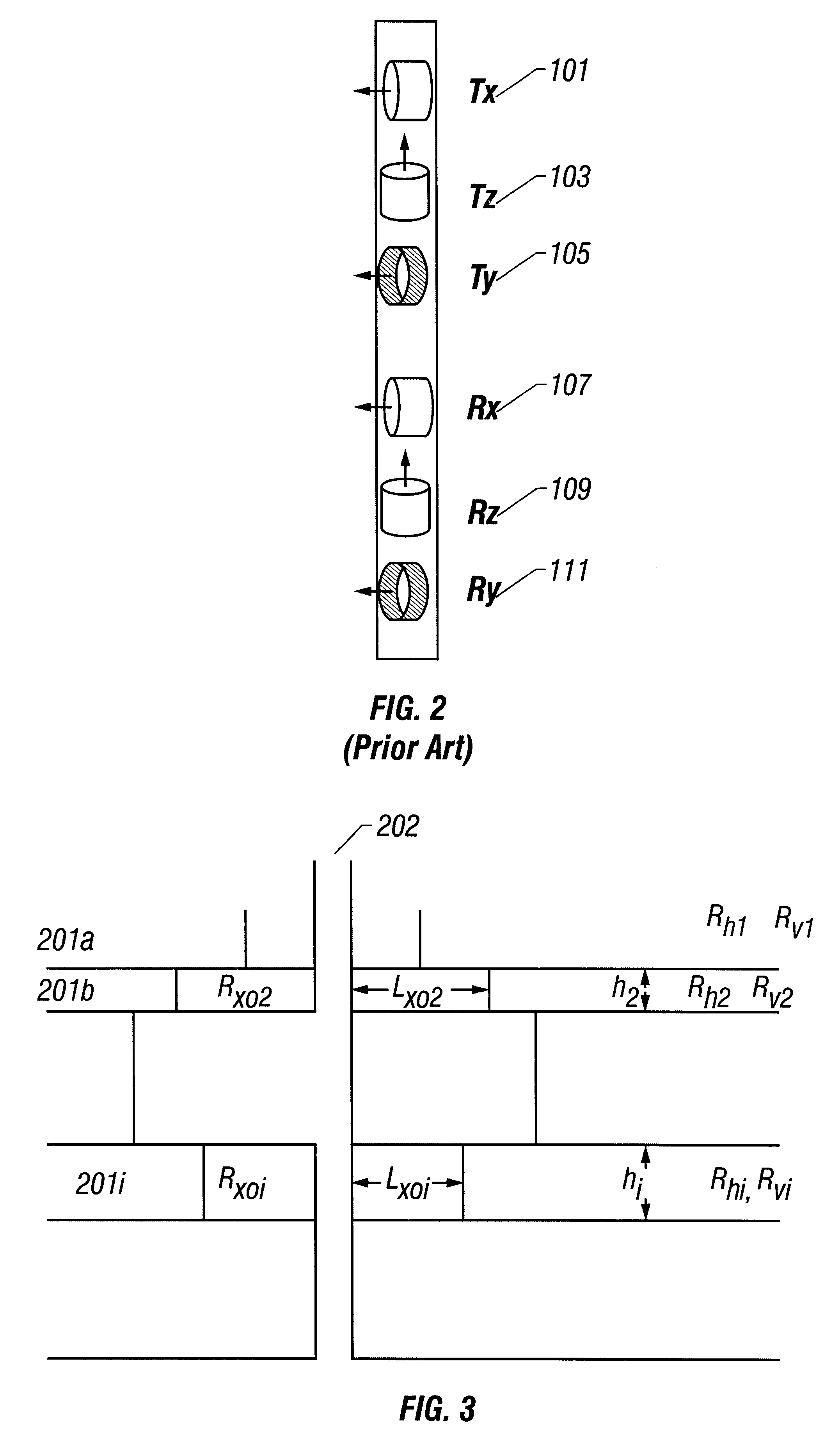
Next, an illustrative example of the use of the pseudo 2-D inversion scheme on a simple but yet realistic and typical 2-D model is shown. The formation parameters of the layered anisotropic background model are shown in Table 1. The borehole diameter is 12.25 inches, and the borehole mud resistivity is 0.1 Ohm-m. The synthetic example shown is typical for well logging applications, when seawater is used as drilling fluid.

The parameter resolution can be studied qualitatively with `back-transformed singular values` (BTSV) (Jupp and Vozoff, 1977; Hordt, 1992). To define the BTSV, we begin with the singular value decomposition of the Jacobian matrix J, J=USV.sup.T, where U is the orthonormal matrix of data eigenvectors, V is the orthonormal parameter eigenvector matrix and S is the diagonal matrix containing the singular values of J.sup.T J (e.g., Jupp and Vozoff, 1974).

Now, we introduce the diagonal matrix K, composed of the normalized singular values (k.sub.j =s.sub.j / s(l)j=1,2 . . ....


PUM


Abstract

A fast, efficient and accurate pseudo 2-D inversion scheme for resistivity determination of an anisotropic formation uses data from a tool (3DEX) comprising three transmitters and three corresponding receivers sampling the formation in a plurality of spatial directions. An initial model of the formation including invasion zones is obtained using a conventional multifrequency and / or multispacing logging tool. A pseudo 2-D inversion scheme combines an accurate full 2-D forward solution of the synthetic responses of the earth model with a 1-D approximation of the sensitivity matrix of the horizontally layered anisotropic background model. The timesaving compared to a regular 2-D inversion scheme can be tremendous. The applicability of this scheme is important in cases when borehole and near-zone effects do not allow an interpretation based on 1-D inversion. A comparison of the pseudo 2-D inversion scheme versus a full 2-D inversion using a realistic synthetic example shows that the pseudo 2-D inversion scheme performs as well as the full 2-D inversion, but in a much shorter time.

Description

1. Field of the InventionThe invention is related generally to the field of interpretation of measurements made by well logging instruments for the purpose of determining the properties of earth formations. More specifically, the invention is related to a method for inversion of measurements made by multi-component induction or propagation sensors.2. Background of the ArtElectromagnetic induction and wave propagation logging tools are commonly used for determination of electrical properties of formations surrounding a borehole. These logging tools give measurements of apparent resistivity (or conductivity) of the formation that when properly interpreted are diagnostic of the petrophysical properties of the formation and the fluids therein.The physical principles of electromagnetic induction resistivity well logging are described, for example, in, H. G. Doll, Introduction to Induction Logging and Application to Logging of Wells Drilled with Oil Based Mud, Journal of Petroleum Technol...

Claims


Application Information

Patent Timeline
Patent Type & Authority Patents(United States)
IPC IPC(8): G01V3/28G01V3/18G01V11/00
CPCG01V11/00G01V3/28
Inventor KRIEGSHAUSER, BERTHOLDMCWILLIAMS, STEVEFANINI, OTTOYU, LIMING
Owner BAKER HUGHES INC
Why Eureka
Eureka Blog
Learn More