Carcass reinforcement for aircraft tires

a technology for aircraft tires and carcasses, applied in the field of tires, can solve the problems of increased hysteresis losses, low fatigue strength of beads, and higher operating temperatures

Inactive Publication Date: 2003-07-22
MICHELIN RECH & TECH SA
View PDF9 Cites 5 Cited by
  • Summary
  • Abstract
  • Description
  • Claims
  • Application Information

AI Technical Summary

Benefits of technology

While providing the number of plies necessary and sufficient to withstand the tensions due to the internal inflation pressures imposed on the tire, the above arrangement furthermore permits a substantial reduction of the number of reinforcing layers under the annular reinforcing elements serving to anchor the carcass reinforcement. This leads to a reduction of the inside diameter of the annular reinforcing elements and, hence, a better positioning of the reinforcing elements, with, consequently, a better distribution of the contact pressures between the seats and flanges of the beads of the tire and the rim seats and flanges, and more uniform clamping on the rim, the net effect being an improved fatigue strength of the beads.
It has been found that, to improve the behavior in the water bursting test, it is advantageous for the axially inner plies which are not turned up to be chosen from the axially innermost plies, that is to say, the plies innermost in the tire.

Problems solved by technology

The severe conditions under which tires for aircraft are used are such that the fatigue strength of the beads is low, particularly at the upturns of the carcass reinforcement.
The large number of carcass plies, generally formed from reinforcing elements made of aliphatic polyamide, which number is necessary to bear the tension due to the test pressure which, as known, must be equal to four times the service pressure, obviously results in the multiplication of the number of the free ends of reinforcing elements, the multiplication of the interfaces between plies, greater hysteresis losses and thus higher operating temperatures, all factors which are liable to increase the fatigue of the beads and limit their fatigue strength.

Method used


Image

  • Carcass reinforcement for aircraft tires
  • Carcass reinforcement for aircraft tires

Examples


Embodiment Construction

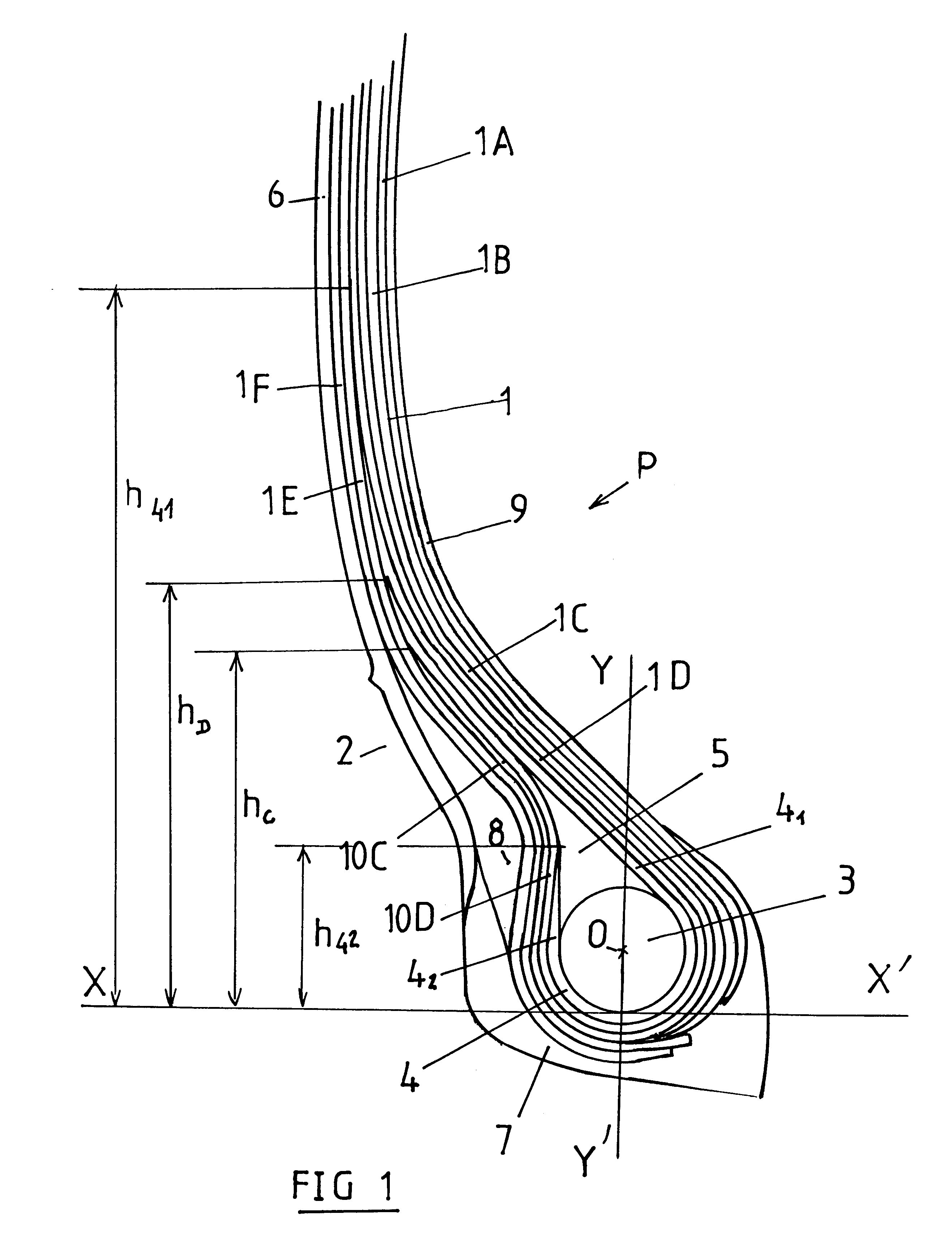
The example given is that of a tire of standard size 46.times.17.0 R 20 (standards of the Tire and Rim Association). The carcass reinforcement 1 is formed from six plies 1A to 1F of radial textile cords made of aliphatic polyamide (in particular of 188 / 3 or 210 / 3 nylon cords). Radial cords of an aircraft tire are to be understood as meaning cords forming angles which may be in the range 90.degree..+-.15.degree. with the circumferential direction. Among the six plies, the four plies 1A to 1D are referred to as axially inner plies, in the sidewalls and beads. Two (IC and ID) of the four plies are wound in each bead 2 around an annular reinforcing element in the form of a bead wire 3, having a circular cross-section in the embodiment shown, from the inside to the outside of the tire P, to form upturns 10C and 10D.

The ends of the upturns 10C and 10D are at respective heights hC and hD from the base of the bead, represented by a line XX' parallel to the axis of rotation of the tire and p...


PUM


Abstract

An aircraft tire, inflated to a high pressure, comprising a tread connected to two beads 2 by way of two sidewalls 6, each bead having at least one annular reinforcing element 3, a crown reinforcement and a radial carcass reinforcement 1 comprising a number of axially inner plies 1A to 1D greater than or equal to two, which radial carcass reinforcement plies have textile reinforcing elements. Among the axially inner plies 1A to 1D, at least half the total number of axially inner plies 1C, 1D are turned up in each bead about at least one annular reinforcing element 3, at least one and at most three of the remaining axially inner plies 1A, 1B being not turned up in any of the beads and having ends situated radially below a straight line XX' parallel to the axis of rotation of the tire and passing through the radially innermost point of the cross-section of the annular reinforcing element 3 and axially inside a straight line YY', perpendicular to the axis of rotation and passing through the center of gravity O of the cross section of the annular reinforcing element 3.

Description

BACKGROUND OF INVENTION1. Technical Field of the InventionThe present invention relates to a tire with radial carcass reinforcement intended to bear heavy loads and inflated to relatively high pressures, and in particular a tire for aircraft.2. The Related ArtThe radial carcass reinforcements of such tires generally have several plies of textile reinforcing elements, which are anchored in each bead to at least one annular reinforcing element and in most cases to a single bead wire. The reinforcing elements of the carcass reinforcements are wound around the bead wire from the inside to the outside, forming upturns with respective ends spaced radially from the axis of rotation of the tire. The severe conditions under which tires for aircraft are used are such that the fatigue strength of the beads is low, particularly at the upturns of the carcass reinforcement.A significant improvement in performance is obtained by separating the carcass reinforcement plies into two groups. The first...

Claims


Application Information

Patent Timeline
Patent Type & Authority Patents(United States)
IPC IPC(8): B60C19/00B60C15/00B60C9/08
CPCB60C15/0018B60C15/0072B60C2200/02
Inventor ROGET, CYRILLESUAREZ, FERNANDO
Owner MICHELIN RECH & TECH SA
Why Eureka
Try Eureka