
Ducted vehicles particularly useful as VTOL aircraft

a ducted vehicle and aircraft technology, applied in the field of vehicles, can solve the problems of not enabling the maximum deck surface of the vehicle, adding to the overall weight of the vehicle, and hovering of the vtol vehicle with sometimes zero forward airspeed, etc., to increase the efficiency of the lift force, facilitate entry and exit, and increase the effect of the lift force produced

Inactive Publication Date: 2003-05-27
URBAN AERONAUTICS
View PDF9 Cites 135 Cited by
  • Summary
  • Abstract
  • Description
  • Claims
  • Application Information

AI Technical Summary

Benefits of technology

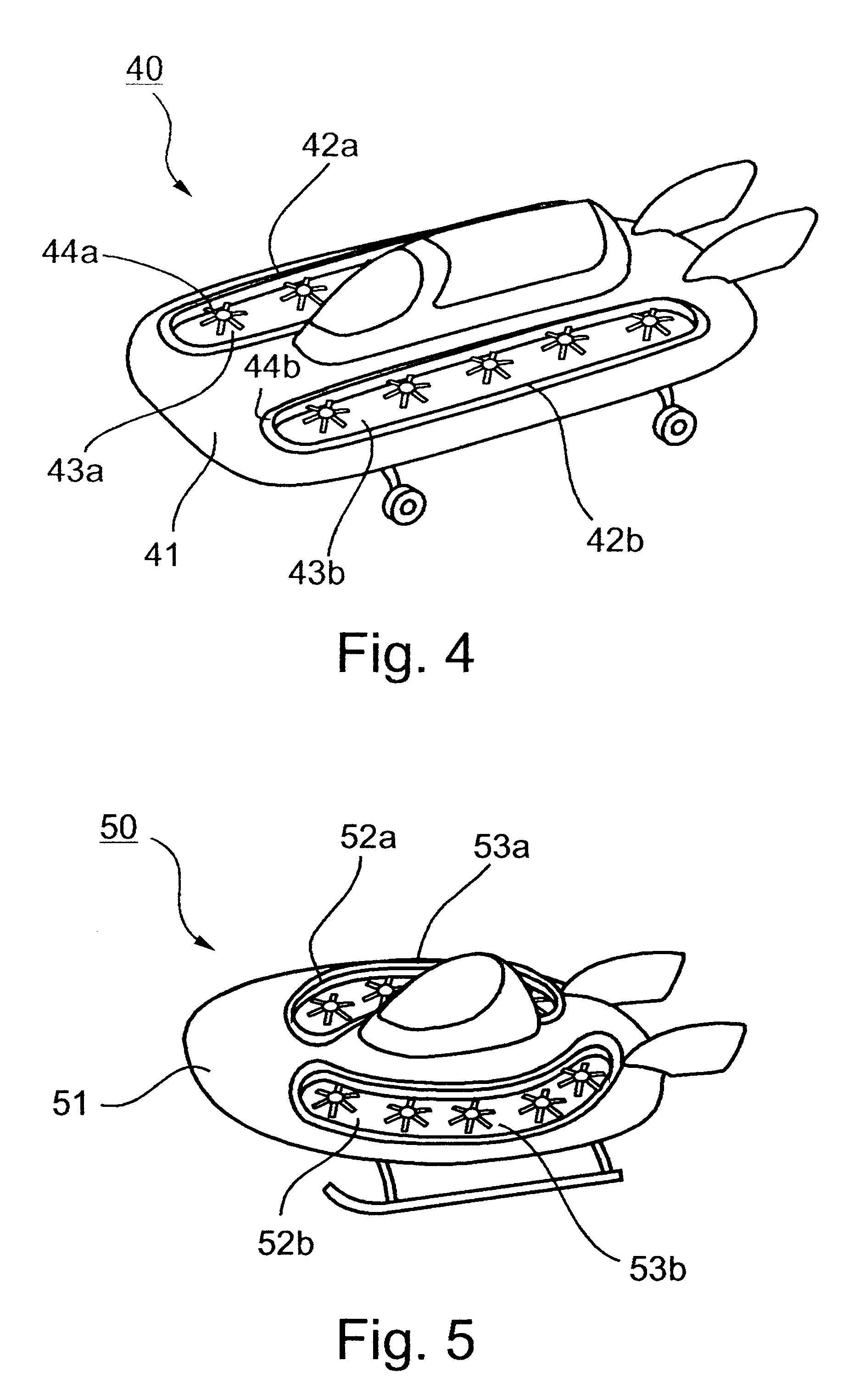
According to one aspect of the present invention, there is provided a vehicle movable within an ambient fluid, comprising: a vehicle body; a first group of rotary propeller propulsion units mounted on one side of the vehicle body, each of the rotary propeller propulsion units being oriented to produce a downward flow of the fluid and thereby an upward lift force applied to that side of the vehicle body; a second group of rotary propeller propulsion units mounted on the opposite side of the vehicle body, each of the latter rotary propeller propulsion units being oriented to produce a downward flow of the fluid, and thereby an upward lift force applied to the opposite side of the vehicle body; a first elongated duct on the one side of the vehicle body enclosing all the rotary propeller propulsion units of the first group and having an upper end and a lower end projecting past the upper and lower ends of the enclosed rotary propeller propulsion units; and a second elongated duct, separate from the first elongated duct, located on the opposite side of the vehicle body and enclosing all the rotary propeller propulsion units of the second group, the second elongated duct having an upper end and a lower end projecting past the upper and lower ends of the second group of rotary propeller propulsion units; the cross-sectional area of each of the first and second elongated ducts being larger than the sum of the cross-sectional areas of the plurality of rotary propeller propulsion units enclosed by the respective elongated duct, to increase the efficiency whereby the lift force is produced by the respective rotary propeller propulsion units; the ends of the first and second elongated ducts being spaced from each other to facilitate entry and exit from the vehicle.
According to further features in the preferred embodiments of the invention described below, the upper inlet end of each elongated duct is circumscribed by a curved surface which guides smoothly the fluid flow into the duct and also further augment the lift force produced by the propulsion units, through the Bernoulli effect.
As will be described more particularly below, the invention is implemented in a VTOL aircraft in which the propulsion units are rotary propellers. While using a plurality of propellers within a single duct will have some detrimental effect on the thrust augmentation achieved by the duct because of the inability to completely avoid gaps between propellers and the duct walls, such an arrangement still provides some augmentation, while keeping the propellers protected inside the fuselage, while at the same time enabling a simple control scheme to be used for controlling the vehicle in flight. It is also believed that, although some regions inside the duct have no propellers directly acting on the air stream, the overall flow through the duct will be relatively uniform as long as the propellers are not separated too far from each other.
It is believed, therefore, that a vehicle constructed in accordance with the foregoing features, particularly a VTOL aircraft including propellers as the propulsion units, will provide a number of important advantages including the following: since the propellers are inside ducts and within the confines of the fuselage, the arrangement provides protection to the propeller blades, as well thrust augmentation by the duct. In addition, the total duct cross-sectional area is larger than the sum of the separate cross-sectional areas of each propeller. Further, the thrust of each propeller can be changed, so that a simple scheme for creating control movements can be obtained.

Problems solved by technology

The main difficulty stems from the fact that, contrary to fixed wing aircraft which accelerate on the ground until enough airspeed is achieved on their flight surfaces, VTOL vehicles hover with sometimes zero forward airspeed.
However, each propeller has its own duct which adds to the overall weight of the vehicle; and the area between the propellers is blocked to the air flow which does not enable maximum deck surface of the vehicle to be utilized for lift.
Such an arrangement, among other disadvantages, makes it difficult for the passenger or passengers to enter and exit

Method used


Image

  • Ducted vehicles particularly useful as VTOL aircraft
  • Ducted vehicles particularly useful as VTOL aircraft
  • Ducted vehicles particularly useful as VTOL aircraft

Examples


Embodiment Construction

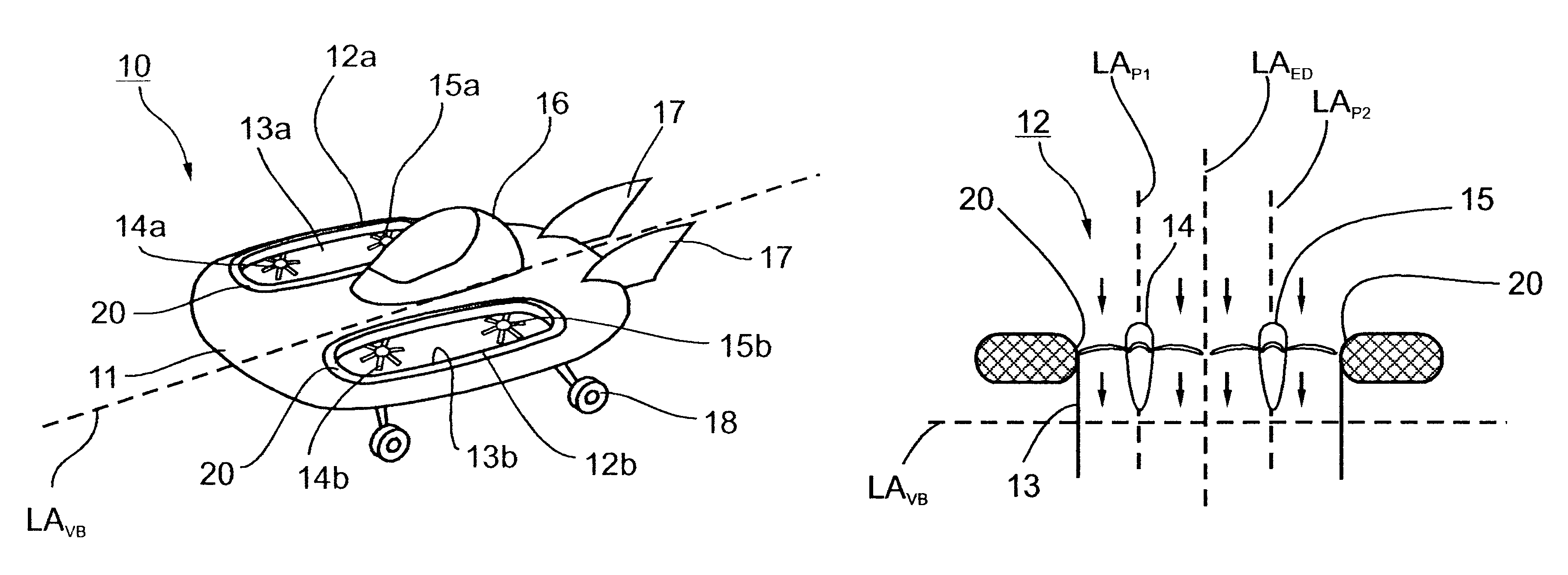
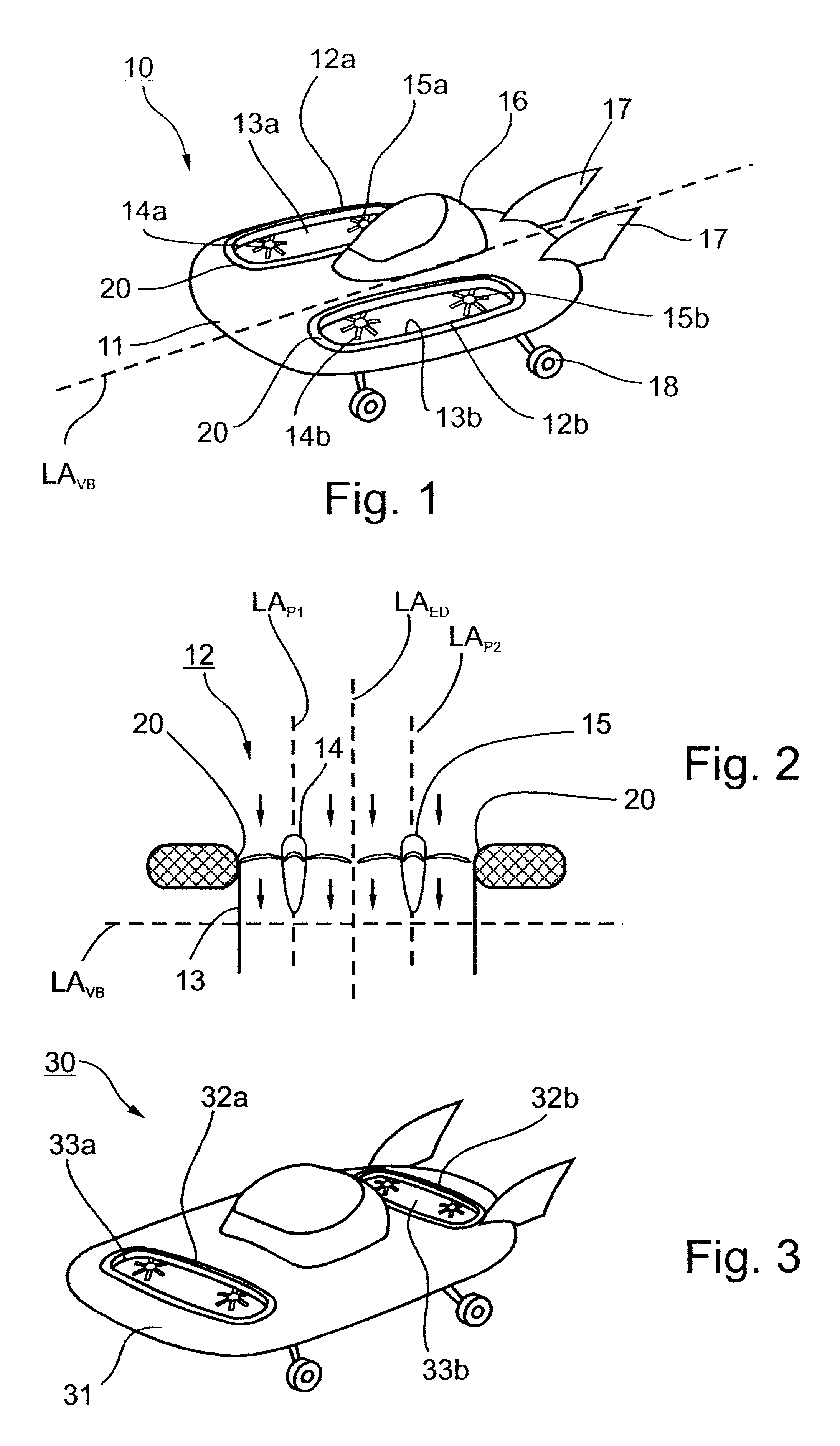
FIG. 1 illustrates a VTOL (Vertical Take-off and Landing) aircraft vehicle, generally designated 10, including a vehicle body or fuselage 11 carrying two ducted propulsion units 12a, 12b on opposite sides of the horizontal longitudinal axis LA.sub.VB of the vehicle body. Each of the ducted propulsion units 12a, 12b includes an elongated duct 13a, 13b, and a pair of rotary propellers 14a, 14b and 15a, 15b, respectively mounted within and enclosed by the respective elongated duct 13a, 13b. The vehicle illustrated in FIG. 1 further includes a payload, in the form of a cabin 16, a pair of vertical stabilizers 17, and landing gear 18.

The ducted propulsion units 12a, 12b, in the vehicle illustrated in FIG. 1 include rotary propellers 14a, 14b, 15a, 15b mounted with their rotary axes perpendicular to the horizontal longitudinal axis LA.sub.VB of the vehicle body. This is more particularly shown in the diagram of FIG. 2 wherein the ducted propulsion unit is generally designated 12, and the ...


PUM


Abstract

A VTOL aircraft (or other vehicle such as a sea vehicle) includes a pair of elongated ducts on opposite sides of the vehicle body, and a plurality of powered propellers (or other propulsion units such as jet engines) mounted within and enclosed by each of the elongated ducts, such as to produce an upward lift force to the vehicle. Each of the elongated ducts has a short transverse dimension slightly larger than the diameter of the blades of each propeller enclosed thereby, and a large transverse dimension slightly larger than the sum of the diameters of the blades of all the propellers enclosed thereby.

Description

FIELD AND BACKGROUND OF THE INVENTIONThe present invention relates to vehicles movable within an ambient fluid, such as air or water. The invention is particularly useful in VTOL (Vertical Take-off and Landing) aircraft, and is therefore described below with respect to this application.Many different types of VTOL aircraft have been proposed where the weight of the vehicle in hover is carried directly by rotors or propellers, with the axis of rotation perpendicular to the ground. One well known vehicle of this type is the conventional helicopter which includes a large rotor mounted above the vehicle fuselage. Other types of vehicles rely on propellers that are installed inside circular cavities, shrouds, ducts or other types of nacelle, where the propeller or rotor is not exposed, and where the flow of air takes place inside a circular duct. Most ducts have uniform cross-sections with the exit area (usually at the bottom of the duct when the vehicle is hovering) being similar to tha...

Claims


Application Information

Patent Timeline
Patent Type & Authority Patents(United States)
IPC IPC(8): B64C27/20B64C29/00B64C11/00B64C27/00B64C39/00
CPCB64C11/001B64C27/20B64C39/001B64C29/0075B64C29/0033B64U30/26B64U50/14B64U10/20B64C29/0066
Inventor YOELI, RAFI
Owner URBAN AERONAUTICS
Learn More