
Collapsible reclining chair

a reclining chair and collapsible technology, applied in the field of folding chairs, can solve the problems of not incorporating some of the advantages provided by the chair with a rigid frame, the compactness of the chair in the folded position is limited to the size of the rigid frame, and the collapse of the chair

Inactive Publication Date: 2003-04-15
MARX EDWARD MICHAEL
View PDF25 Cites 34 Cited by
  • Summary
  • Abstract
  • Description
  • Claims
  • Application Information

AI Technical Summary

Problems solved by technology

The compactness of the chair in the folded position is, however, limited to the size of the rigid frame U.S. Pat. No. 4,514,009(Vanderminden et al, 1985).
This type of a collapsible design provides a chair that can be collapsed into a compact configuration, however, it does not incorporate some of the advantages provided by the chair with a rigid frame.
One of the disadvantages the collapsible chair has is that there is no longer a rigid frame to stretch the seat material between.
This design causes the seat to sag, because there is no rigid structure separating the leg bars.
Another disadvantage is that the mechanism for reclining the chair can not be located in a convenient location because there is no rigid structure on which to provide one.

Method used


Image

  • Collapsible reclining chair
  • Collapsible reclining chair
  • Collapsible reclining chair

Examples


Embodiment Construction

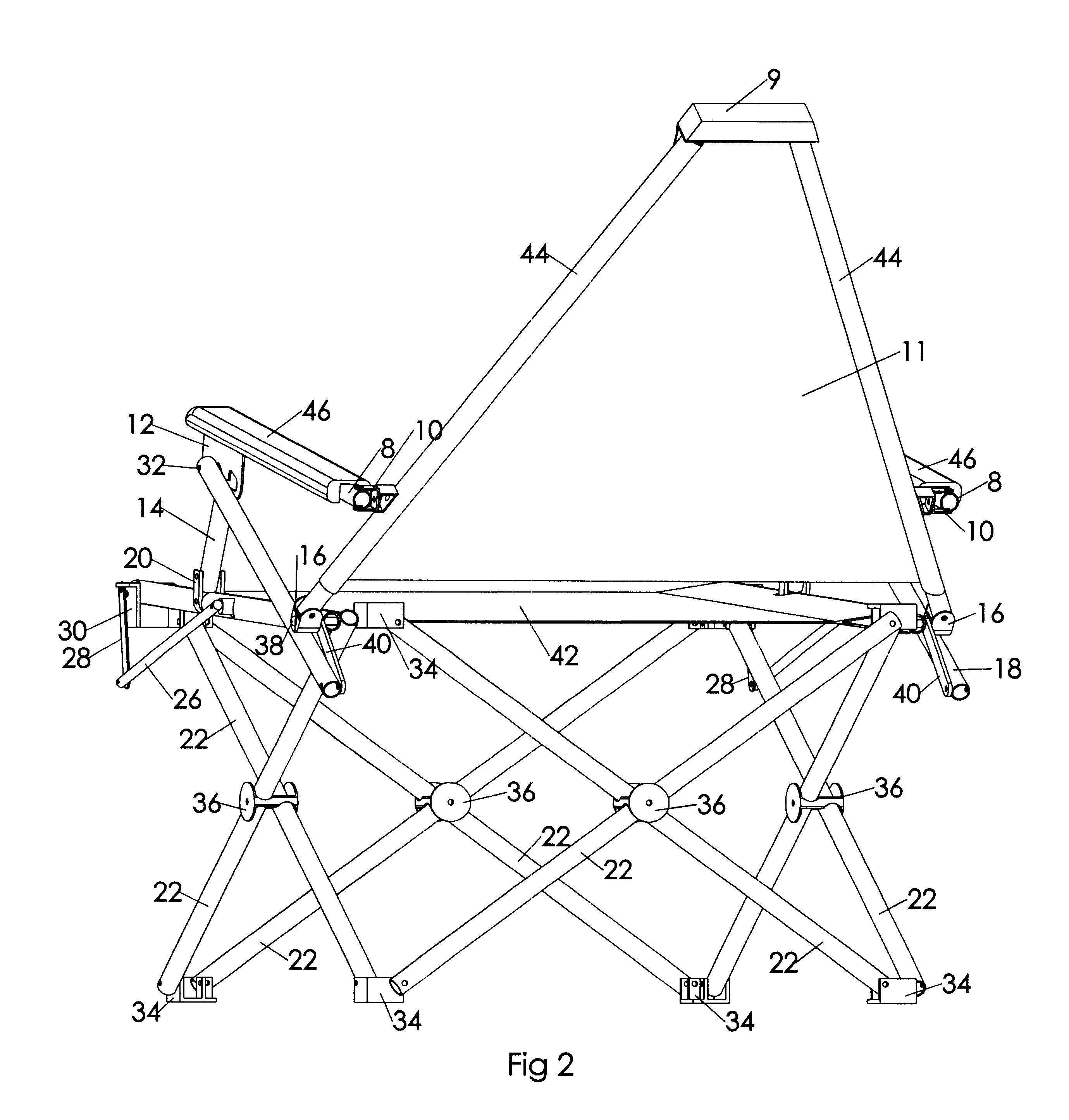
FIG. 1 shows a perspective view of a basic version of the chair. Leg tubes 22 are pivotally attached at their centers and held in an X position by leg braces 36. Leg tubes 22 are pivotally attached perpendicular to the ends of other legs tubes 22 at the lower ends and are pivotally attached at the rear upper ends by corner fasteners 34. The upper ends of two front leg tubes 22 are pivotally fastened perpendicular to two side leg tubes 22 by seat clips 30. Seat clips 30, corner fasteners 34, and leg braces 36 permit rotation of leg tubes 22 to a folded position where the leg tubes 22 are parallel to each other as shown in FIG. 4A.

Parallel seat tubes 24 pivot about a rear pivot 38 and fasten to the front of the chair by clipping into seat clips 30. Flexible material for a seat cover 42 is looped between seat tubes 22 allowing seat tubes 22 to rotate. Guides long 26 are pivotally attached at the center of seat tubes 24 and are pivotally attached to guides short 28 which are attached to...


PUM


Abstract

A chair with four sets of leg tubes(22) consisting of two leg tubes(22) attached at their centers in an X position which fold into a collapsed position with leg tubes(22) nearly parallel to each other. Seat tubes(24), and back tubes(44) are pivotally attached to the upper ends of leg tubes(22) at the rear of the chair. Seat tubes(24) are connected to leg tubes(22) at the front of the chair by seat clips(30). This configuration of the chair in the open position, provides a stable structure for the attachment of a seat cover(42) and for the attachment of a mechanism for reclining back tubes(24) and back cover(11). Arm braces(18) extending from the top of leg tubes(22) at the rear of the chair, and connected to vertical tubes(14) extending from near the center of seat tubes(24) support arm tubes(8), which are attached to back tubes(44). Back tubes (44) recline by moving arm tubes(8) to different positions in slots in arm plates(12) attached near the front of arm tubes(8). Seat tubes(24) unclip from the front of the chair, and seat tubes(24), seat cover(42), back tubes(44), and back cover(11) pivot up and back to a position where seat tubes(24) and back tubes(44) are nearly parallel to leg tubes(22), forming a compact folded configuration.

Description

STATEMENT REGARDING FEDERALLY SPONSORED RESEARCH OR DEVELOPMENTNot ApplicableREFERENCE TO A MICROFICHE INDEXNot ApplicableBACKGROUND OF INVENTIONThis invention is related to the field of folding chairs, especially chairs which can be collapsed into a compact position and easily transported.Folding chairs have been designed with a rigid square back frame pivotally attached to the rear of a rigid square seat frame. These chairs typically have rigid u-shaped legs pivotally attached to the seat frame and arms. When the chair is folded the back frame folds parallel to the seat frame while the legs and arms fold parallel to the back frame. This configuration provides a chair with a rigid frame, which allows the seat material to be stretched taught between parallel frame members, and allows a mechanism which reclines the backrest of the chair to be located conveniently at the arm rests U.S. Pat. No. 5,144,03(Allen, 1894). The compactness of the chair in the folded position is, however, lim...

Claims


Application Information

Patent Timeline
Patent Type & Authority Patents(United States)
IPC IPC(8): A47C4/00A47C4/50A47C4/28
CPCA47C4/50A47C4/286
Inventor MARX, EDWARD MICHAEL
Owner MARX EDWARD MICHAEL
Learn More