
Surface emitting laser device with monolithically integrated monitor photodetector

Inactive Publication Date: 2003-03-18
KOREA ADVANCED INST OF SCI & TECH
View PDF4 Cites 23 Cited by
  • Summary
  • Abstract
  • Description
  • Claims
  • Application Information

AI Technical Summary

Benefits of technology

is to provide a surface emitting laser device with a monolithically integrated monitor photodetector, which is capable of effectively cutting off photocurrent resulting from spontaneous emission light while allowing only photocurrent, resulting from laser light, to flow through the monitor photodetector, thereby achieving an accurate control for the power of light emitted from a surface emitting laser thereof.
In the surface emitting laser device according to the present invention, photocurrent resulting from a large part of spontaneous emission light emitted from the surface emitting laser is removed by nonradiative recombination centers located at respective interfaces between the lower insulating layer and the intrinsic semiconductor layer and between the intrinsic semiconductor layer and the upper insulating layer. Accordingly, it is possible to accurately control the power of light emitted from the surface emitting laser device through the laser window by feeding back a detect signal outputted from the monitor photodetector to the surface emitting layer, as drive current, via an automatic power control circuit.

Problems solved by technology

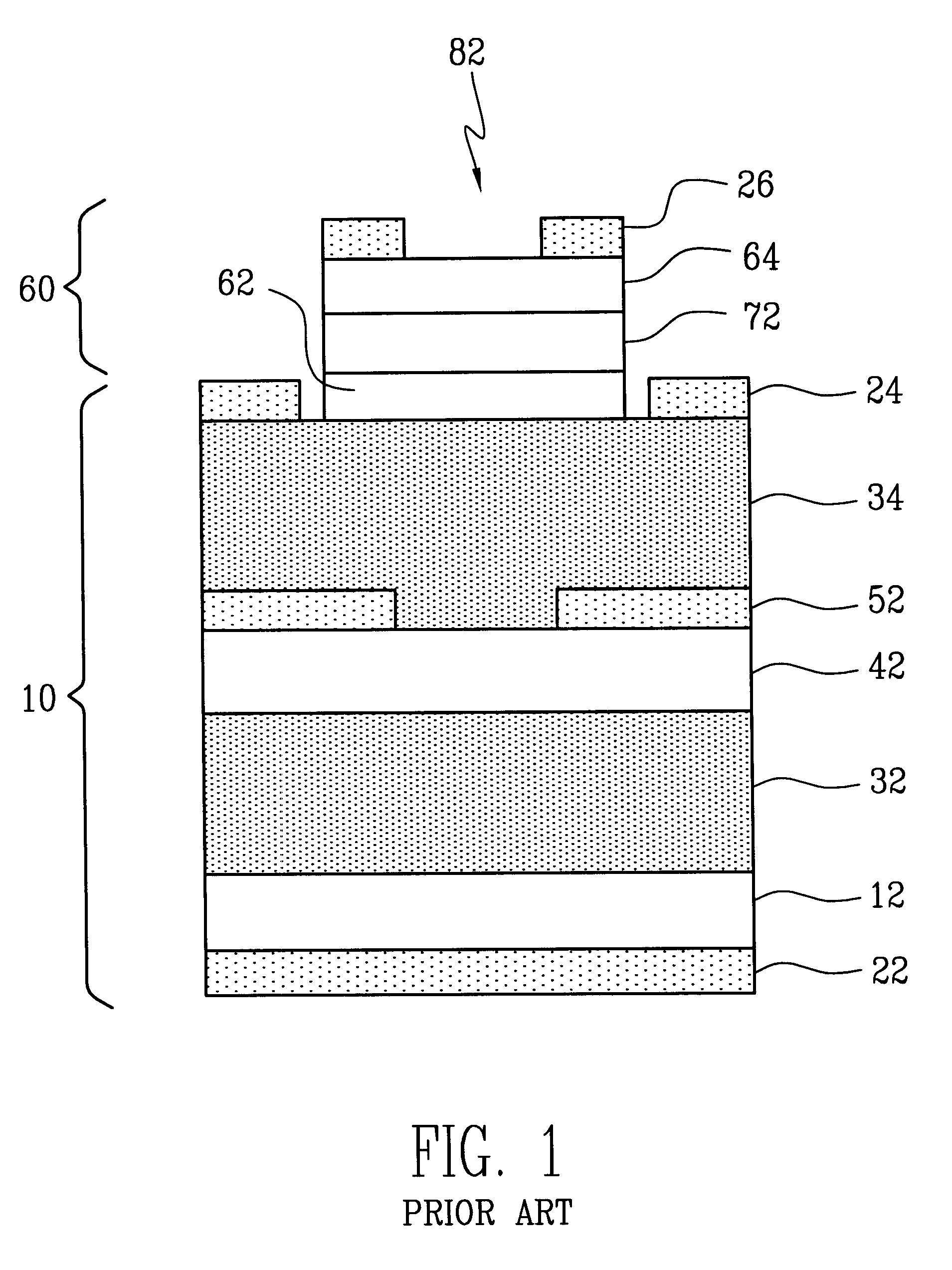
As a result, it is difficult to accurately control the power of light emitted from the surface emitting laser (10), based on the detect signal outputted from the monitor photodetector (60), because of the spontaneous emission light.

Method used


Image

  • Surface emitting laser device with monolithically integrated monitor photodetector
  • Surface emitting laser device with monolithically integrated monitor photodetector
  • Surface emitting laser device with monolithically integrated monitor photodetector

Examples


Embodiment Construction

Now, preferred embodiments of the present invention will be described in detail, with reference to the annexed drawings.

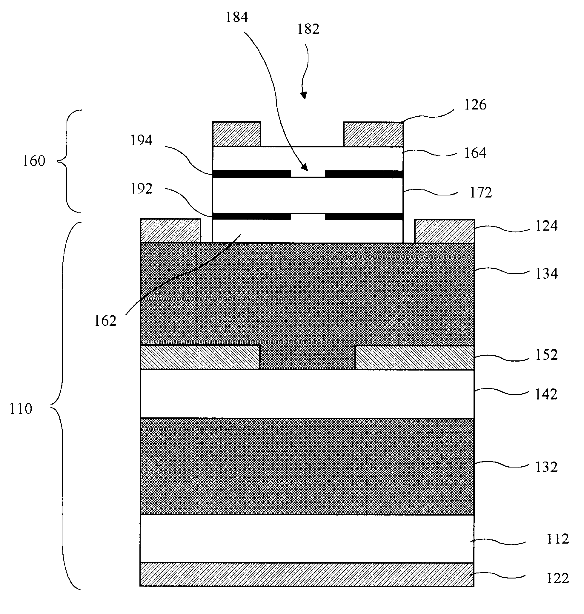
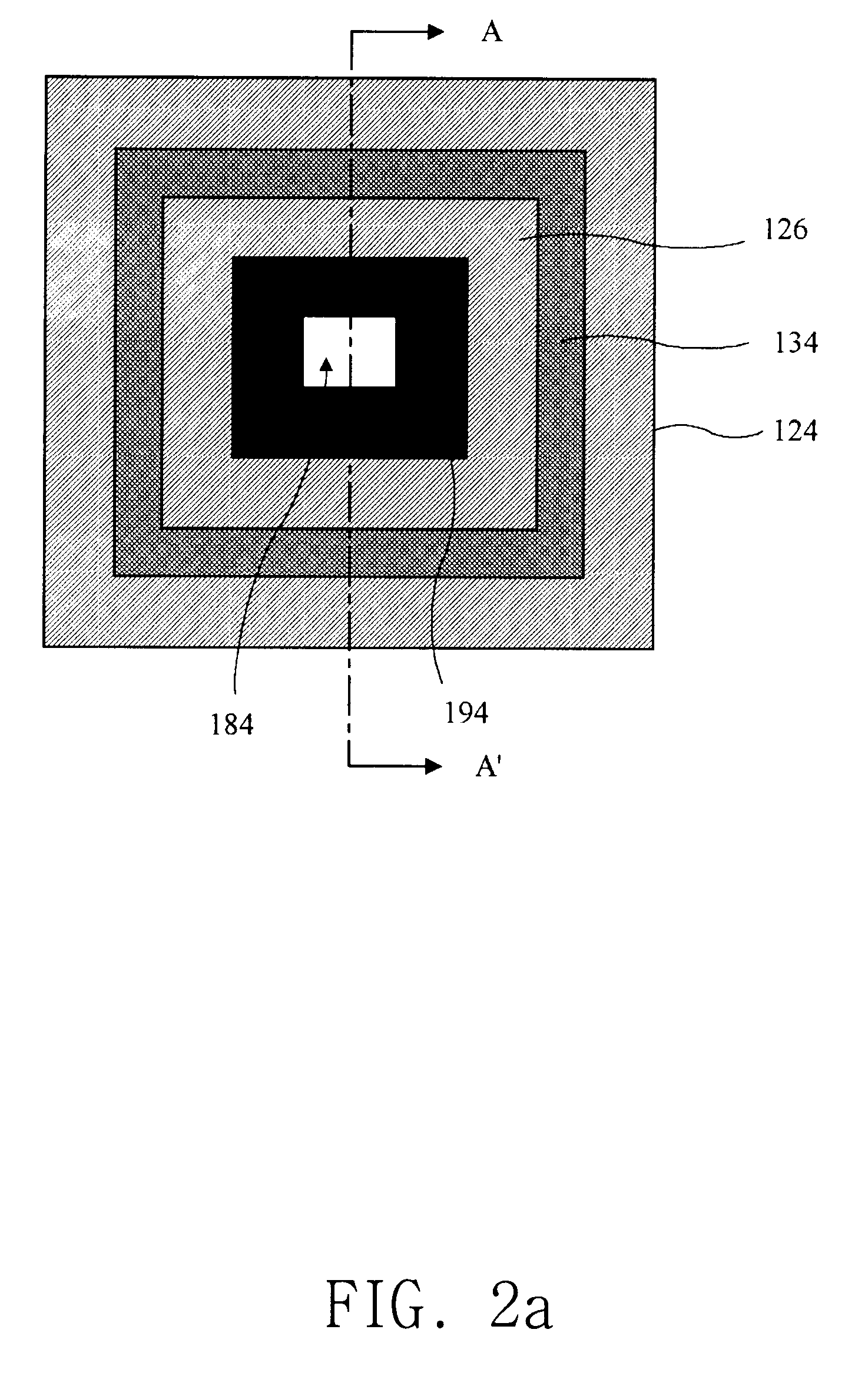
FIGS. 2a and 2b illustrate a surface emitting laser device with a monolithically integrated monitor photodetector in accordance with an embodiment of the present invention, respectively. FIG. 2a is a plan view of the surface emitting laser device whereas FIG. 2b is a cross-sectional view taken along the line A-A' of FIG. 2b.

Referring to FIGS. 2a and 2b, the surface emitting laser device includes a surface emitting laser (110) for emitting light in a direction, along which semiconductor layers are grown, and a monitor photodetector (160) formed on the surface emitting laser (110). The monitor photodetector (160) serves to partially receive light emitted from the surface emitting laser (110), thereby detecting the power of light emitted from the surface emitting laser (110).

The surface emitting laser (110) includes a substrate (112) made of GaAs doped with Si, and a ...


PUM


Abstract

Disclosed is a surface emitting laser device with a monolithically integrated monitor photodetector, which is combined with an automatic power control circuit, thereby being capable of more accurately controlling the surface emitting laser output power. A method is also disclosed, which is adapted to fabricate the surface emitting laser device. In accordance with, the present invention, the surface emitting laser device includes insulating layers each sandwiched between an intrinsic semiconductor layer and a doped semiconductor layer in a monitor photodetector adapted to partially absorb light emitted from a surface emitting laser, thereby outputting a detect signal for the light. The insulating layers serve to remove photocurrent resulting from spontaneous emission light emitted from the surface emitting laser. By this configuration, it is possible to accurately control the power of light emitted from the surface emitting laser through a laser window.

Description

1. Field of the InventionThe present invention relates to a surface emitting laser device with a monolithically integrated monitor photodetector and a method for fabricating the same, and more particularly to a surface emitting laser device with a monolithically integrated monitor photodetector, which is combined with an automatic power control circuit, thereby being capable of more accurately controlling the surface emitting laser output power. The present invention also relates to a method for fabricating such a surface emitting laser device with a monolithically integrated monitor photodetector.2. Description of the Related ArtAs is well known, a surface emitting laser (SEL) has been highlighted as light emitting devices. Such a surface emitting laser is configured to emit light in a direction along which semiconductor layers are grown. In this regard, an array of surface emitting lasers can be integrated on a single substrate. Such a surface emitting laser also has an advantage ...

Claims


Application Information

Patent Timeline
IPC IPC(8): H01S5/00H01S5/026H01S5/183H01S5/30H01S5/0683
CPCH01S5/0264H01S5/18311H01S5/1835H01S5/18338H01S5/18333H01S5/30
Inventor LEE, YONG HEEHAN, IL YOUNG
Owner KOREA ADVANCED INST OF SCI & TECH
Learn More