Dual mode phone architecture utilizing a single transmit-receive switch
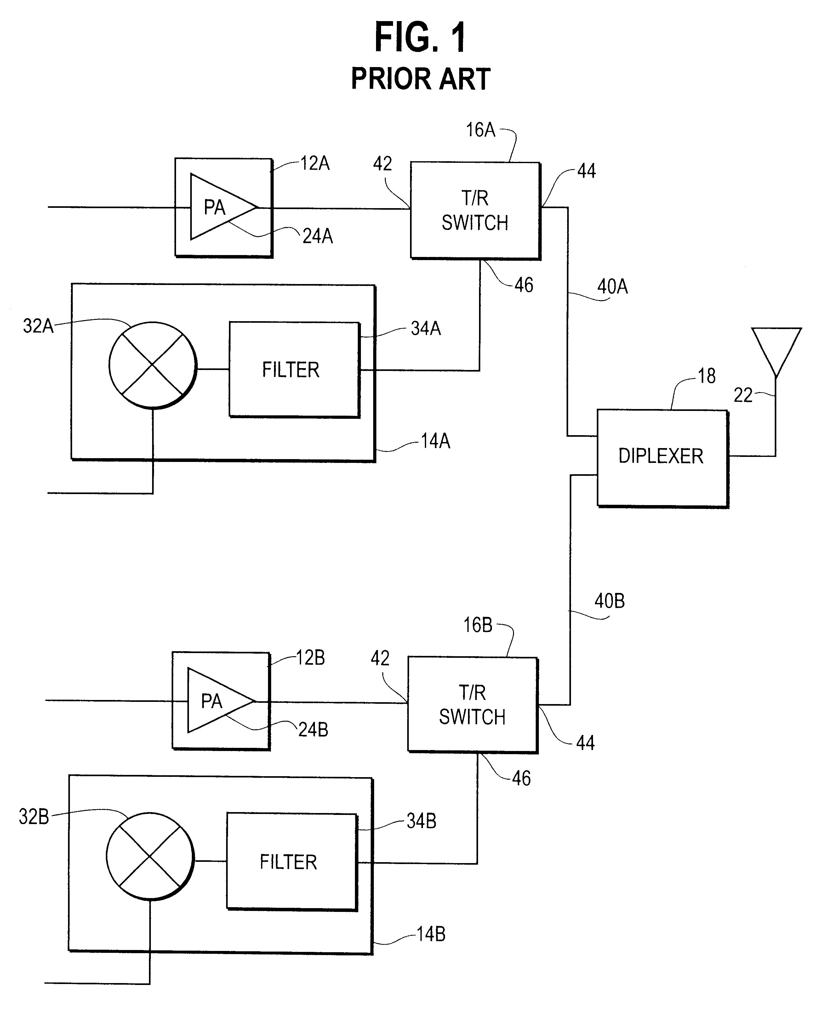
a dual-mode phone and switch technology, applied in telephonic communication, substation equipment, electrical equipment, etc., can solve the problems of high cost, high monetary and circuit board real estate costs of a dual-mode phone design, switch 16a and b,
- Summary
- Abstract
- Description
- Claims
- Application Information
AI Technical Summary
Problems solved by technology
Method used
Image

Examples
Embodiment Construction
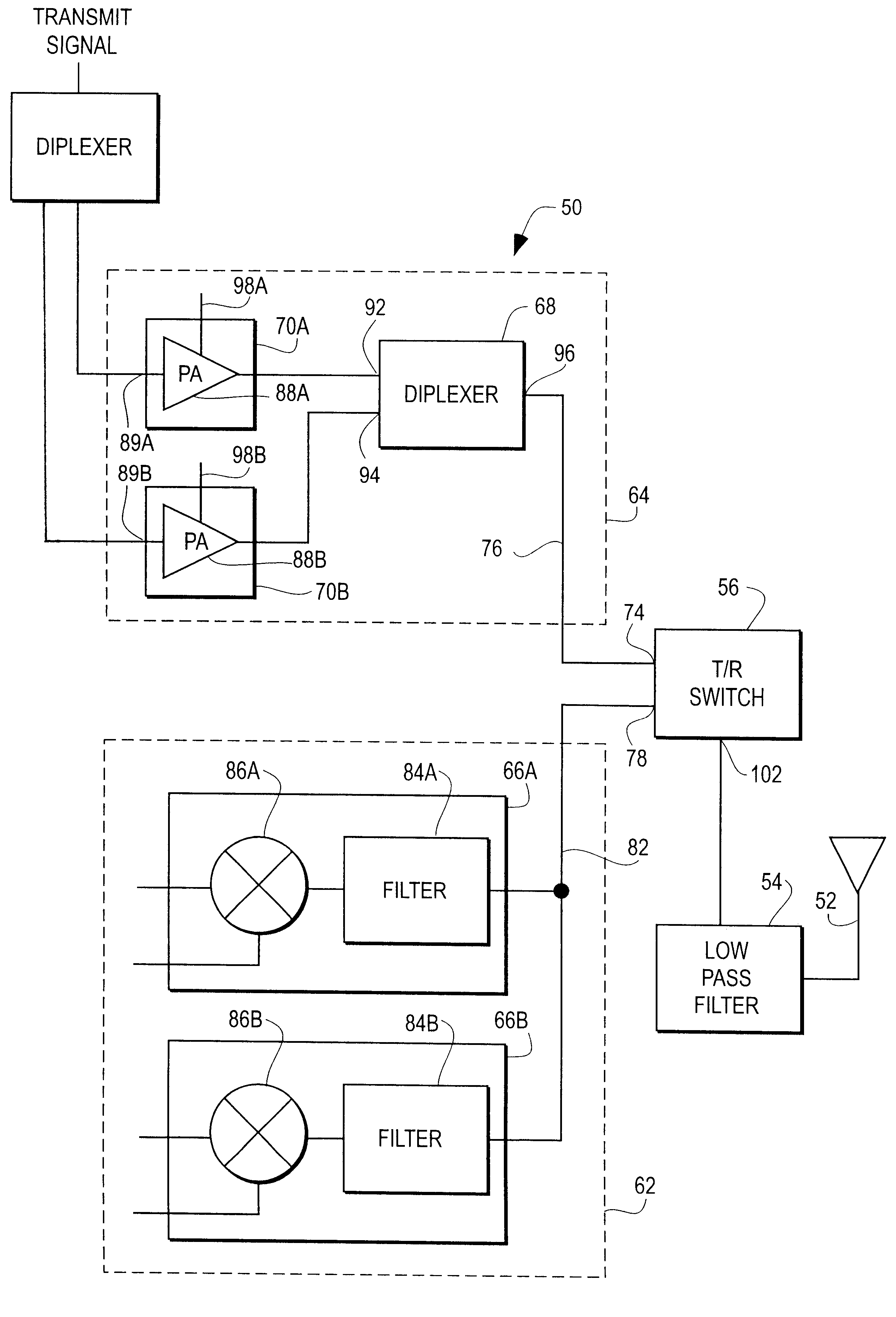
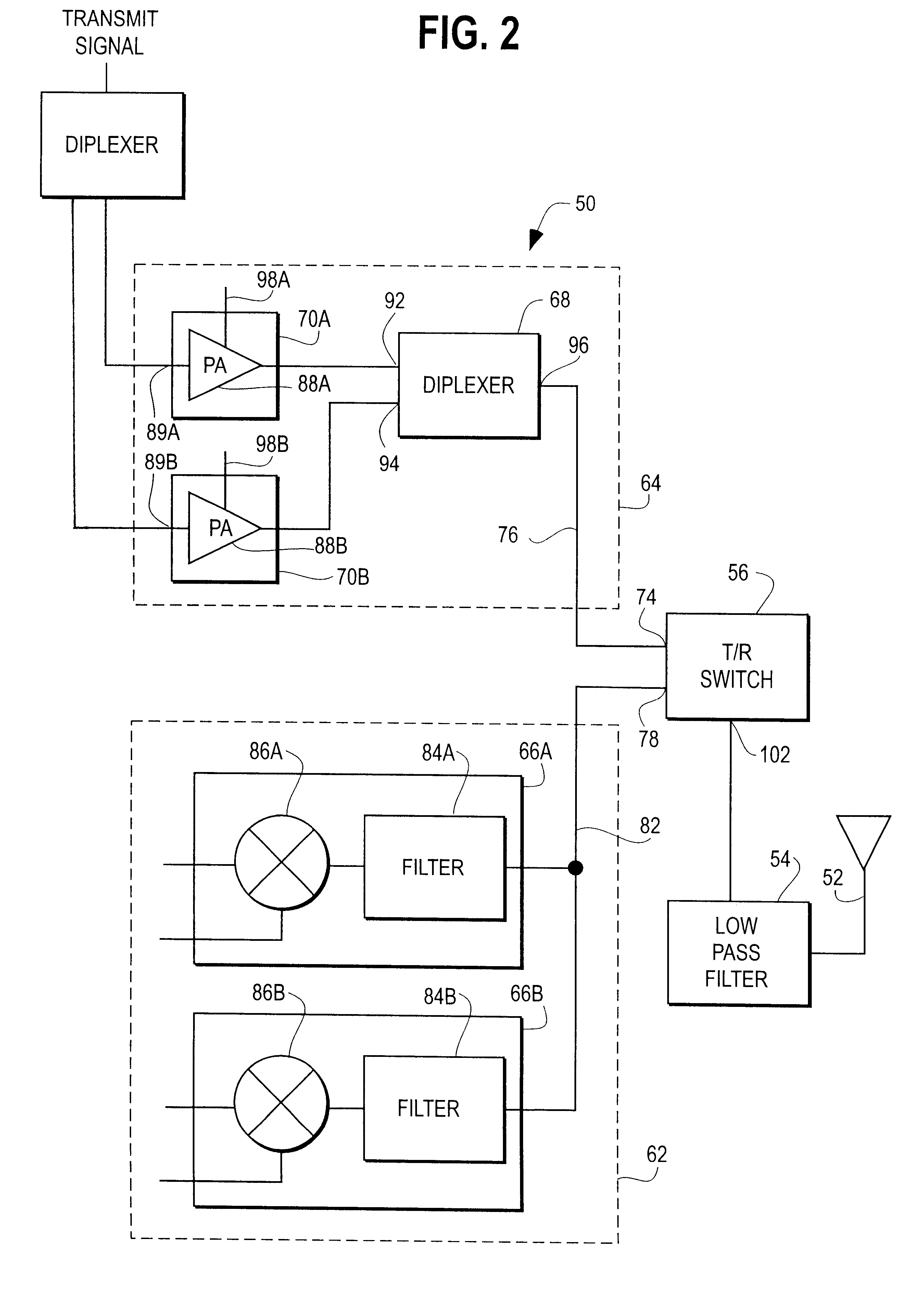
With reference to FIG. 2, a dual mode telephone system 50 includes an antenna 52, a low pass filter 54, a transmit-receive switch 56, a receive unit 62, and a transmit unit 64. Receive unit 62 includes a GSM receive circuit 66A and a DCS receive circuit 66B. Transmit unit 64 includes a diplexer 68, a GSM transmit circuit 70A, and a DCS transmit circuit 70B.
Transmit-receive switch 56 has a transmit input 74 coupled to a transmit path 76 of unit 64 and a receive output 78 coupled to a receive path 82 of unit 62. Receive circuit 66A includes a filter 84A and a LNA mixer 86A. Similarly, receive circuit 66B includes a filter 84B and a LNA mixer 86B. Filter 84A is preferably tuned to the GSM band and coupled to path 82. Filter 84B is preferably tuned to the DCS band and coupled to path 82.
Transmit circuit 70A includes a power amplifier 88A, and transmit circuit 70B includes a power amplifier 88B. Diplexer 68 has a GSM input 92 coupled to amplifier 88A and a DCS input 94 coupled to amplifi...
PUM
 Abstract
Description
Claims
Application Information
 - R&D
- Intellectual Property
- Life Sciences
- Materials
- Tech Scout
- Unparalleled Data Quality
- Higher Quality Content
- 60% Fewer Hallucinations
Browse by: Latest US Patents, China's latest patents, Technical Efficacy Thesaurus, Application Domain, Technology Topic, Popular Technical Reports.
© 2025 PatSnap. All rights reserved.Legal|Privacy policy|Modern Slavery Act Transparency Statement|Sitemap|About US| Contact US: help@patsnap.com