
Accumulated detonating cord explosive charge and method of making and of use of the same

a technology of explosive charge and detonating cord, which is applied in the field of accumulated detonating cord explosive charge and method of making and using the same, can solve the problems of high cost of long legwires of such systems, increased handling risk relative to boosters, and high cost of high-energy detonating cord,

Inactive Publication Date: 2003-01-21
DYNO NOBEL INC
View PDF28 Cites 17 Cited by
  • Summary
  • Abstract
  • Description
  • Claims
  • Application Information

AI Technical Summary

Problems solved by technology

The long legwires of such systems are expensive and subject to breakage in lowering and positioning the cast boosters in the borehole.
In addition, the assembly of the primary explosive of the detonators with the secondary explosive cast boosters in the borehole increases the handling risks relative to boosters that do not contain primary explosive materials.
In mining operations, however, the high-energy detonating cord tends to disrupt the bulk (main) explosive charge and is expensive as compared to low-energy detonating cord.
In seismic blasting operations, the use of high-energy detonating cord is not satisfactory because the high-energy detonating cord releases significant energy along paths remote from the points at which energy is released by the cast booster charges, and therefore renders seismic data less precise.
This arrangement requires utilizing a more sensitive explosive in conjunction with a less sensitive one, thereby increasing the risk of accidental initiation of the explosive charge.

Method used


Image

  • Accumulated detonating cord explosive charge and method of making and of use of the same
  • Accumulated detonating cord explosive charge and method of making and of use of the same
  • Accumulated detonating cord explosive charge and method of making and of use of the same

Examples


Embodiment Construction

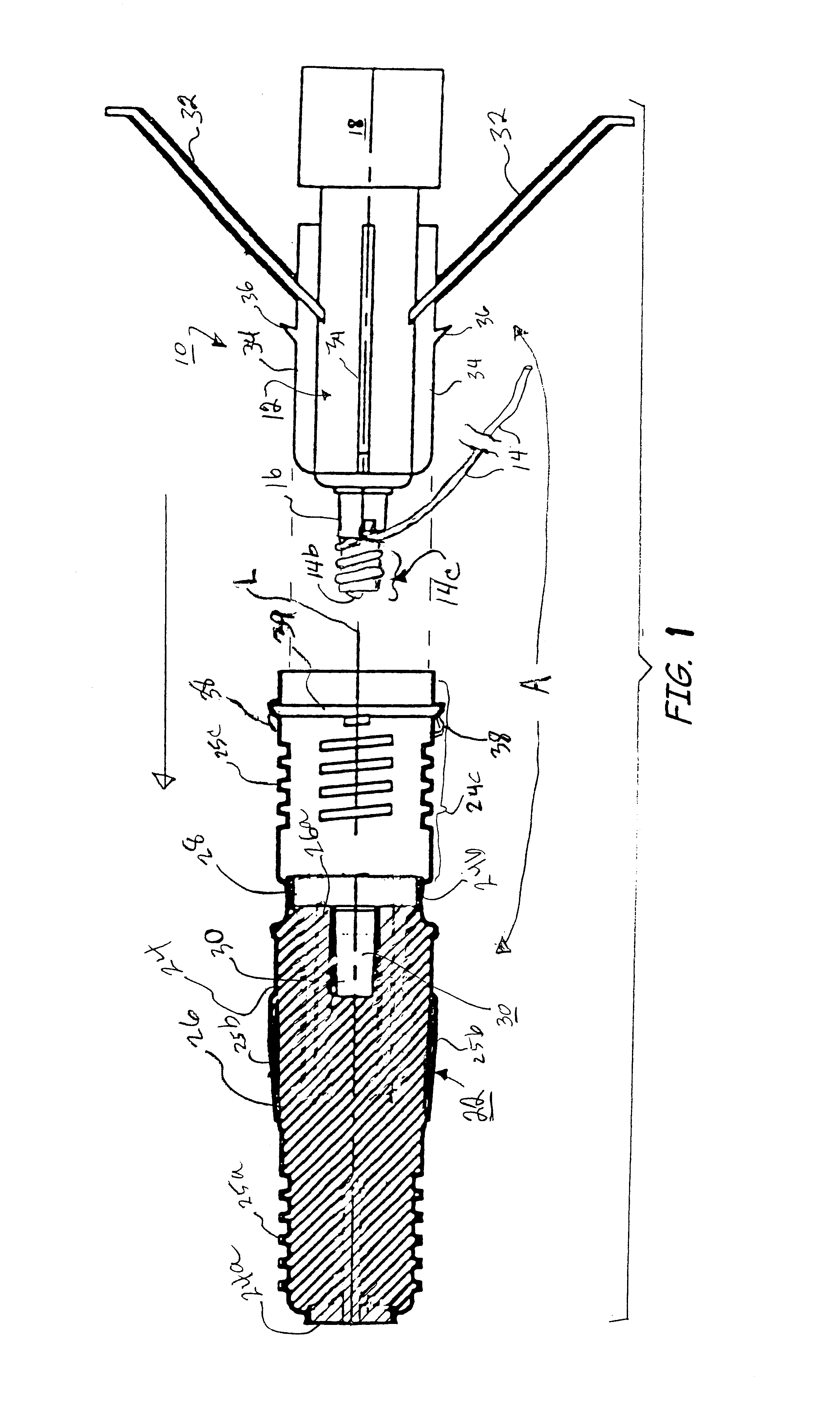
Generally, the present invention provides enhanced reliability in the use of detonating cord, including low-energy detonating cord, as an explosive charge for various functions in which a straight, linearly configured cord would not provide adequate output energy. One such use is for the direct initiation of receptor charges such as a signal transmission line (e.g., another detonating cord) or main explosive charges (e.g., "booster" charges used in boreholes at blasting sites) that are comprised of relatively insensitive explosive materials, e.g., secondary, explosive materials. The present invention provides initiator charges for such receptor charges produced by a method comprising configuring or "accumulating" the detonating cord into a coil comprising a plurality of windings as to increase the amount of explosive material of the cord in a booster charge or other receptor device relative to a linear configuration of the cord, and further provides devices on which the detonating c...


PUM


Abstract

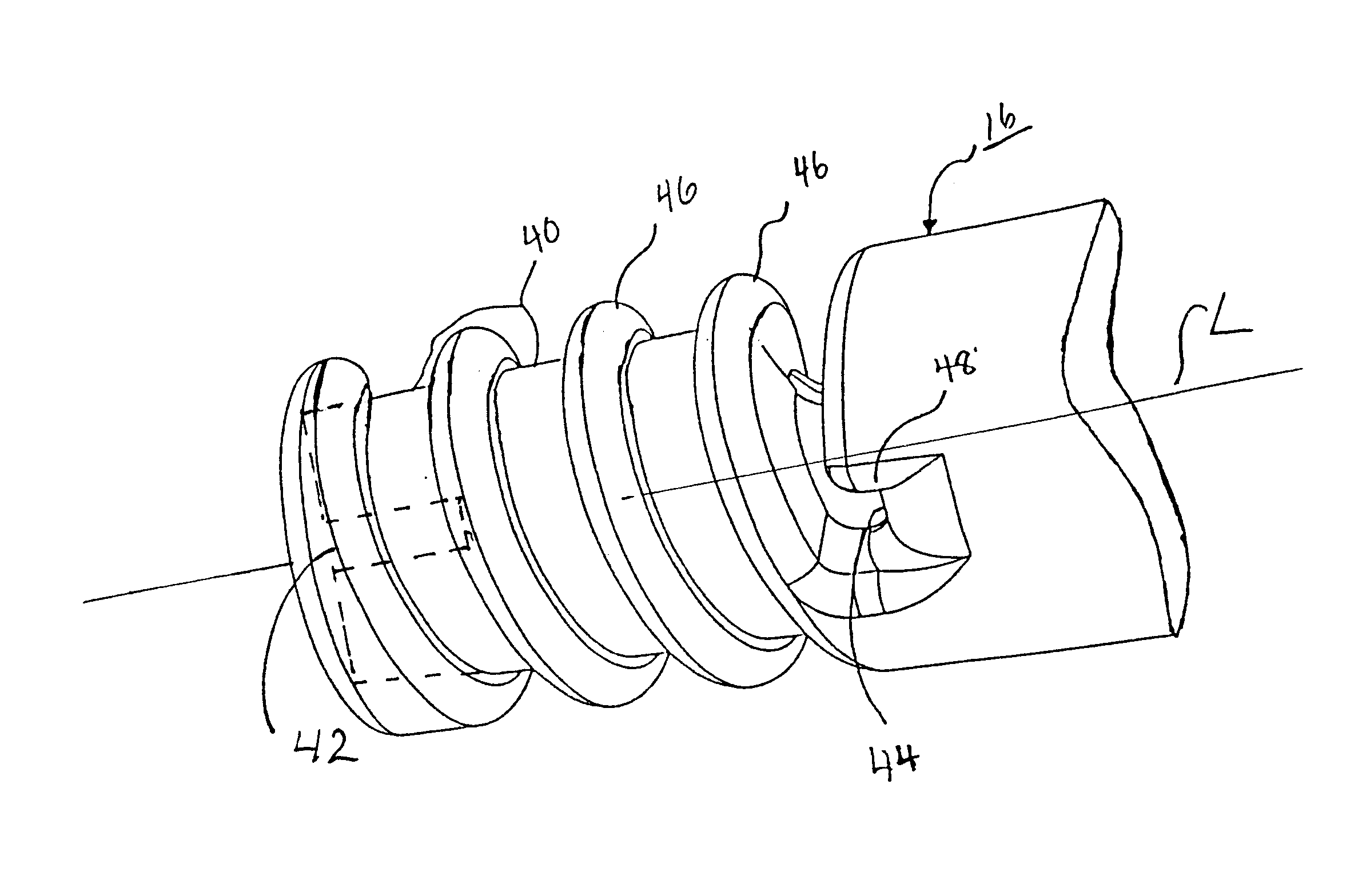
An initiator (14c) for a secondary explosive receptor charge is provided by forming a length of detonating cord (14) into a helical coil containing a plurality of windings with a cutoff barrier provided by, e.g., a separating rib (46) between adjacent windings. The adjacent windings may be not more than about 0.5 inch (12.7 mm) apart. The detonating cord (14) may be wound about a spindle (16) which may optionally provide the separating rib (46). The coil may be a tapered coil which may define a taper angle of e.g., from about 2 to 4 degrees. Alternatively, the coil may be a cylindrical coil, or the cord may be configured in a planar spiral. Optionally, the detonating cord in the helical coil may have a core of explosive material with a loading of less than 15 grains per foot of the cord, e.g., less than 12 grains per foot of the cord, or a loading in the range of from 8 to 12 grains per foot of the cord. The coil may consume about six inches of the cord. Conversely, the detonating cord in the spiral may have a core of explosive material with a loading of at least 2.5 grains per foot, optionally at least 15 grains per foot of the cord.

Description

1. Field of the InventionThe present invention relates to a device and method for forming an explosive charge and explosive from detonating cord and for initiation of receptors such as signal transmission lines and explosive charges.2. Related ArtIn prior art explosive initiation systems it is known to lower into a borehole a cast booster explosive having a cap well into which has been inserted an electric detonator. The electric detonator is fitted with electrically conductive legwires which are long enough to extend from within the borehole to the surface of the blasting site. The long legwires of such systems are expensive and subject to breakage in lowering and positioning the cast boosters in the borehole. In addition, the assembly of the primary explosive of the detonators with the secondary explosive cast boosters in the borehole increases the handling risks relative to boosters that do not contain primary explosive materials.It is also known in the art to utilize, in lieu of...

Claims


Application Information

Patent Timeline
IPC IPC(8): F42B3/00
CPCF42B3/00F42D1/043
Inventor BADGER, FARRELL G.LEE, ROBERT A.BAHR, LYMAN G.SUTULA, JR., DANIEL P.
Owner DYNO NOBEL INC
Learn More