Eureka AIR delivers breakthrough ideas for toughest innovation challenges, trusted by R&D personnel around the world.

Molding equipment for framed sand molds

a mold and equipment technology, applied in the field of mold mold mold mold mold mold mold mold mold mold mold mold mold mold mold mold mold mold mold mold mold mold mold mold mold mold mold mold mold mold mold mold mold mold mold mold mold mold mold mold mold mold mold mold mold mold mold mold mold mold mold mold mold mold mold mold mold mold mold mold mold mold mold mold mold mold mold mold mold mold mold mold mold mold mold mold mold mold mold mold mold mold mold mold mold mold mold mold mold mold mold mold mold mold mold mold mold mold mold mold mold

Inactive Publication Date: 2002-11-05
SINTOKOGIO LTD
View PDF3 Cites 3 Cited by
  • Summary
  • Abstract
  • Description
  • Claims
  • Application Information

AI Technical Summary

Benefits of technology

Also, many effects can be generated by which the centering operations of the molding apparatuses and relevant apparatuses can be decreased, the cost of fixing those apparatuses can be decreased, vibrations transmitted to the base floor can be decreased, and the cost for making the base floor can be decreased.

Problems solved by technology

However, the above molding systems have a disadvantage wherein it is difficult to insulate vibrations that are generated during molding operations from the molding system, so that the environment of a factory is damaged.
Also, there is another disadvantage, wherein it takes a long time to fix those apparatuses at the factory, and the cost for doing so is increases, because accurate centering operations are needed for those apparatuses to prevent them from not working after they are fixed.

Method used


Image

  • Molding equipment for framed sand molds
  • Molding equipment for framed sand molds
  • Molding equipment for framed sand molds

Examples


Embodiment Construction

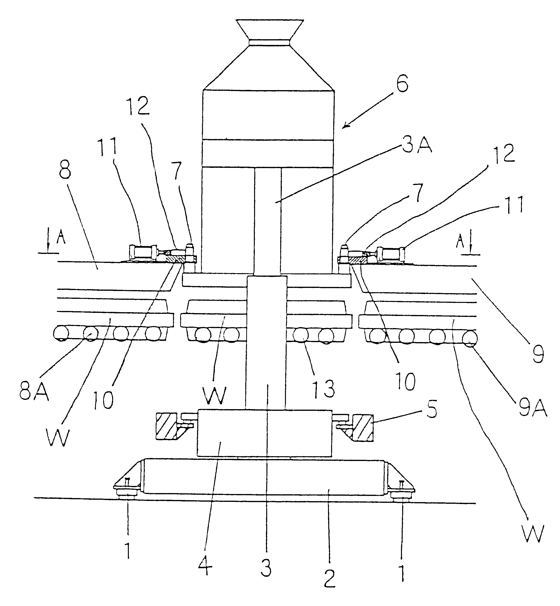
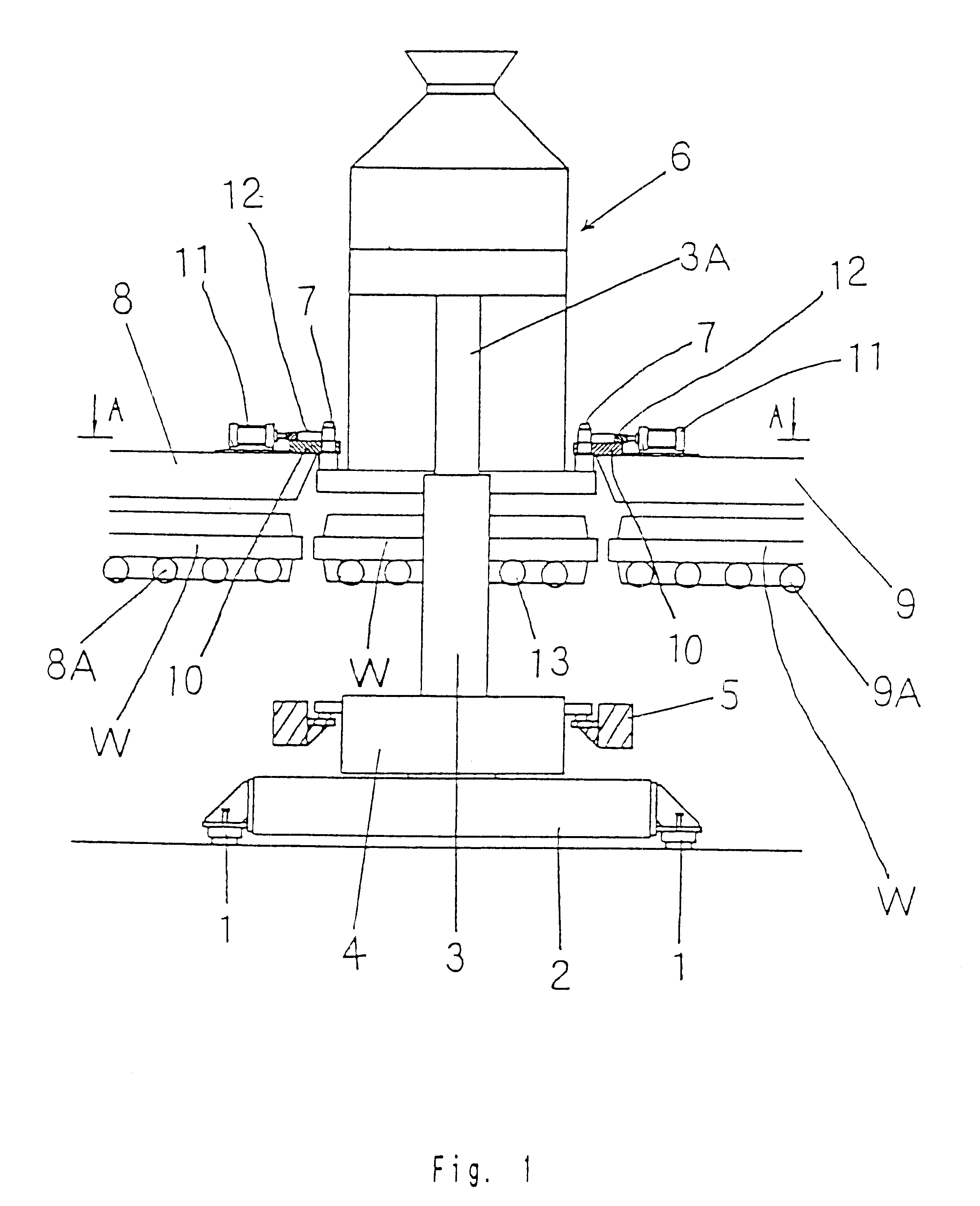
Based on the drawings we below explain one embodiment of this invention. As in FIGS. 1 and 3, a molding support 2 is fixed on a plurality of vibration-insulating pads 1, 1 on a base. As in FIG. 4, which is a sectional view along the line B--B in FIG. 3, a pair of vertical frame-setting cylinders 3, 3 are located on the front and rear ends of the molding support 2. The frame-setting cylinder 3 at the front side (at the lower side in FIG. 4) is also used for the shaft rotating in the. center of a turntable 5, on which two pattern carriers 4, 4 are put.

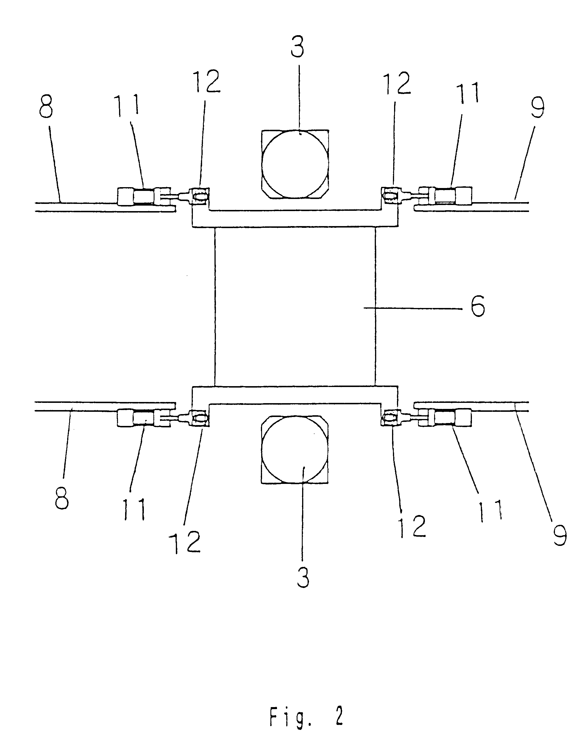
Again as in FIG. 1, a molding head 6 is held on the upper ends of piston rods 3A, 3A of the pair of the frame-setting cylinders 3, 3. Two pairs of centering pins 7, 7 are located at the sides of the lower end of the molding head 6. They project upward. These pins function as a first centering means.

Roller frames 8, 9, which support rollers 8A, 9A that feed in and out molding frames W, are fixed near the sides of the molding head 6 to mai...


PUM

PropertyMeasurementUnit
strengthaaaaaaaaaa
distancesaaaaaaaaaa
timeaaaaaaaaaa

Abstract

A molding system to make a sand mold with a frame is provided to receive the lateral loads generated when molding frames are fed out and in by nearby apparatuses and to prevent vibrations generated during a molding operation from being transmitted to nearby apparatuses, so that the area around a factory is prevented from being degraded and so that apparatuses can be easily affixed. The molding system includes a molding support located on a plurality of vibration-insulating pads, a turntable to allow pattern carriers to be alternately fed in and out above the molding support, a molding head that is located above the turntable and that moves up and down, two pairs of centering pins located on the molding head, roller frames for feeding in and out molding frames from which hang rollers located outside of and near the highest end of the molding head, centering bushes, located above the roller frames for feeding molding frames in and out, that correspond to the two pairs of the centering pins, and a roller hung from the molding head.

Description

This invention relates to a molding system for alternately making upper and lower sand molds in empty molding frames to be fed in a molding apparatus.PRIOR ARTConventional molding systems for sand moldings with frames have had their strength increased by having connected a molding apparatus to both a base and related apparatuses near it to counter the large lateral load generated when the molding frames are fed in and out, or when pattern carriers for upper and lower molding frames are exchanged.However, the above molding systems have a disadvantage wherein it is difficult to insulate vibrations that are generated during molding operations from the molding system, so that the environment of a factory is damaged.Also, there is another disadvantage, wherein it takes a long time to fix those apparatuses at the factory, and the cost for doing so is increases, because accurate centering operations are needed for those apparatuses to prevent them from not working after they are fixed.This...

Claims


Application Information

Patent Timeline
Patent Type & Authority Patents(United States)
IPC IPC(8): B22C23/00
CPCB22C23/00B22C11/00
Inventor KANETO, KIMIKAZUHIRATA, MINORUHADANO, YUTAKA
Owner SINTOKOGIO LTD
Why Eureka
Eureka Blog
Learn More