
Retracting screen frame and mechanism for door or window

a technology for retracting screens and doors, applied in the direction of curtain suspension devices, shutters/movable grilles, insect protection, etc., can solve the problems of insufficient prior art satisfactory treatment of accommodating, affecting the installation and operation of screens, and affecting the free operation of screens, so as to achieve the effect of minimal complexity and construction cost, and improved installation and operation characteristics

Inactive Publication Date: 2002-10-15
LANG RICHARD A
View PDF8 Cites 56 Cited by
  • Summary
  • Abstract
  • Description
  • Claims
  • Application Information

AI Technical Summary

Benefits of technology

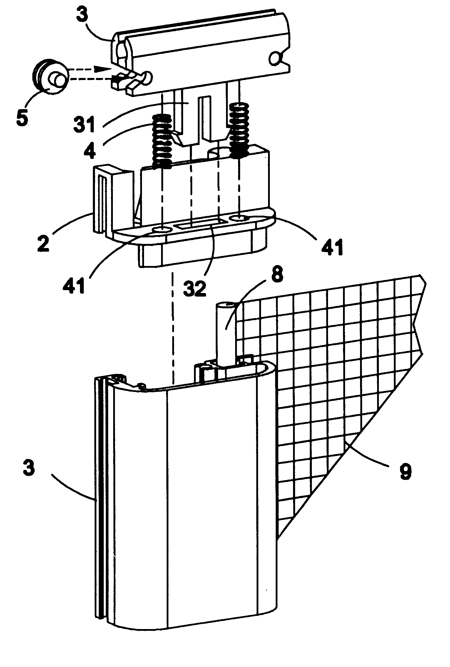
A stabilizing mechanism provided by end caps at both ends of the drawbar is supplied with internally disposed spring loaded roller or low friction sleeves to ride upon the respective top and bottom surfaces of the tracks. The rollers or low friction sleeves and track are kept in contact by the roller housing / low friction sleeve surrounding a portion of the track and roller housing / low friction sleeve spring. Thus, the drawbar rides smoothly across the door opening in response to manual actuation in a vertical posture without binding, while accommodating wide variances in opening dimensions as the screen is opened and closed. A spring mechanism in the screen storage roller assembly serves to retract the screen so the drawbar may be manually or mechanically returned to the roller side in a housing. Either retraction method brings the drawbar into contact with the housing snubbers, cushioning the drawbar inpact with the housing, and reducing the noise and mechanical stress associated with mechanical closing.
Thus the screen door provided by this invention achieves the foregoing objectives of resolving deficiencies of the prior art to provide a different mode of operation, better installation and operation characteristics, and minimal complexity and construction cost.

Problems solved by technology

One significant deficiency of these screens is that the screen installation is dependent on the opening shape, which must be precisely square or provide a perfectly flush surface for mounting.
Thus, for example, a door opening in a building that has settled 1 / 4 inch to one side of the opening would present significant difficulty in installing a properly operating screen inside the opening, and though an exterior flush mount system surmounts some of the difficulty with settled foundations or sills, it is still necessary to install the exterior flush mount absolutely square for proper operation.
The same difficulties occur with window installations where the window opening has become out of plumb or not horizontal.
Additionally, friction in these systems precludes free operation in many cases.
There is no known satisfactory treatment in the prior art of accommodating opening variances in door and window screen assemblies.

Method used


Image

  • Retracting screen frame and mechanism for door or window
  • Retracting screen frame and mechanism for door or window
  • Retracting screen frame and mechanism for door or window

Examples


Embodiment Construction

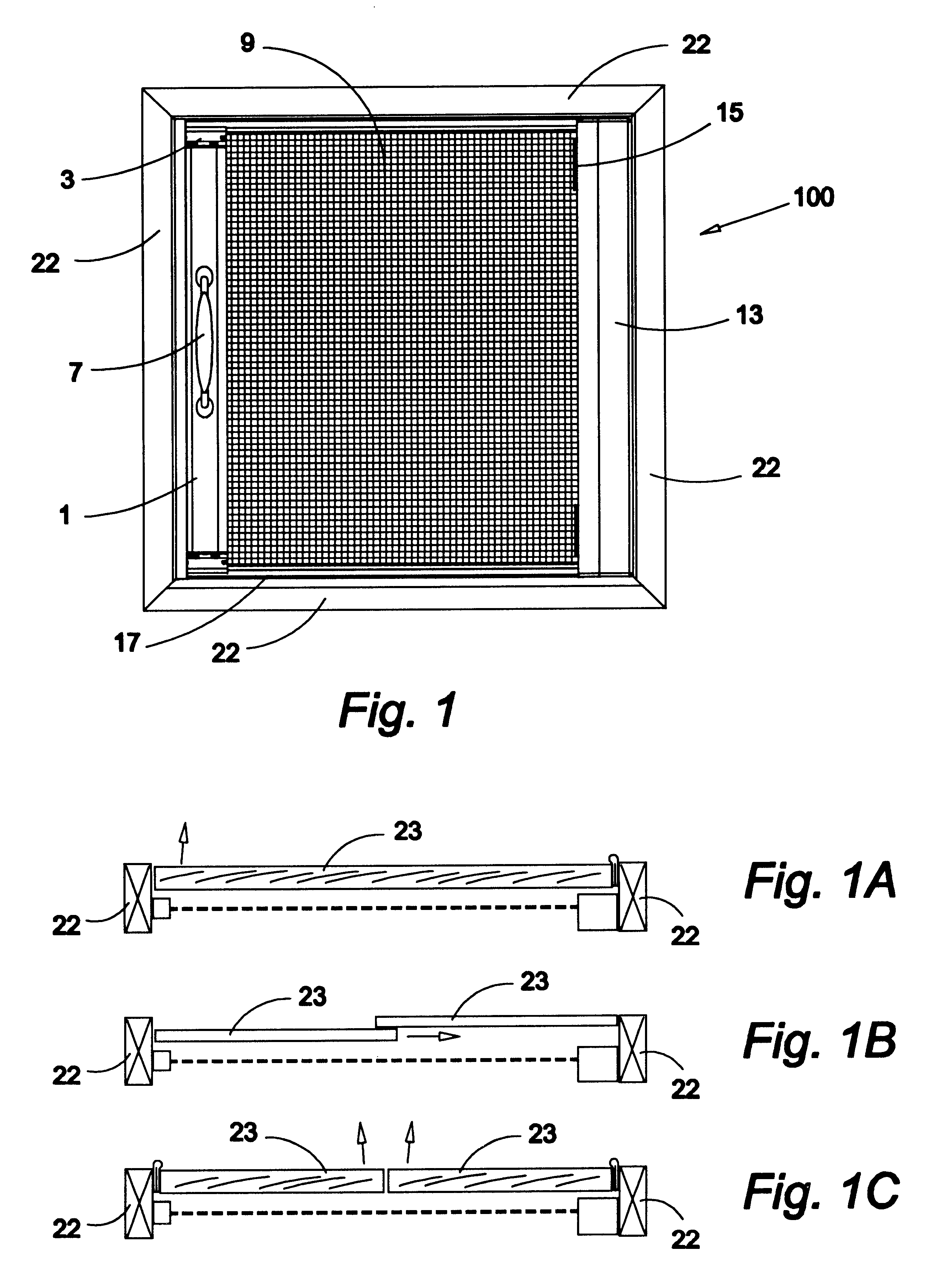
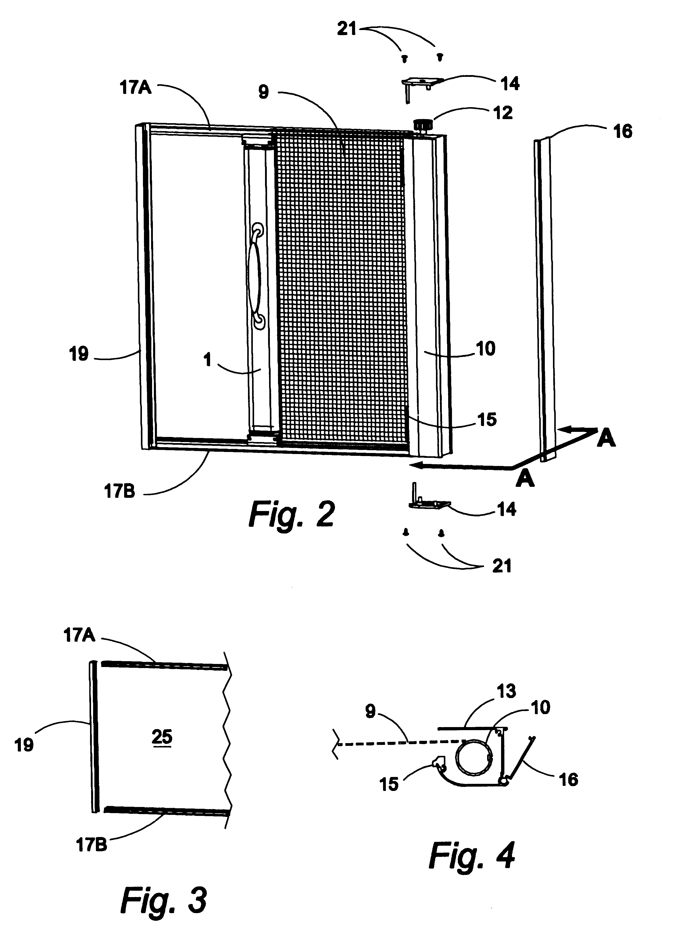
With reference to the accompaning drawings, the roll up screen door 100 of this invention has a screen panel 9 rolled onto a supply roller 10, which is spring biased by the helically coiled spring 11, located within supply roller 10 in supply roller housing end cap 14, thereby to retract the screen panel 9 onto the supply roller 10. Conversly this structure permits the screen panel 9 to be manually with drawn by movement of the drawbar 1 to a closed position when the drawbar 1 is positioned adjacent to a door framework 22 surrounding one or more doors 23. These doors may be either pivoted in nature or sliding doors. Note that a favorable feature of this invention is that the track system 17 may be mounted in a door opening that varies dimensionally from end to end as shown in FIG. 1, thereby allowing the screen to still operate freely.

The mechanism for accommodating various opening dimensions is best visualized from FIGS 5, 7 and 9. Thus, a vertically disposable drawbar 1, having a ...


PUM


Abstract

A retracting screen with its mounting and guiding apparatus for a door or window opening. The apparatus includes a housing from which and into which a screen is rolled, a drawbar for withdrawing the screen from the housing and for latching the screen in a closed position, and tracks for guidance of the drawbar across an opening. The housing is aesthetically mounted within a framed opening. The guidance system for the drawbar is adapted to accommodate slight structural variances in an opening by the cooperation between the drawbar structure and the elements of the track.

Description

This invention relates to a door or window screen, and more particularly to a horizontally moveable door or window screen or a vertical screen for a window. The screen is rolled up onto and unrolled from a vertically or horizontally oriented roller storage site adjacent to a framed door or window.It has heretofore been proposed to roll upon and unroll door or window screens from a vertically disposed door mechanism or window frame. Typical of such prior art are U.S. Pat. No. 4,651,797 issued Mar. 24, 1987 to A. E. Lange for ROLL-UP SCREEN DOOR; U.S. Pat. No. 5,758,704, issued Jun. 2, 1998 to C. K. Elrod for ROLL-UP SCREEN DOOR APPARATUS; and U.S. Pat. No. 6,082,432, issued Jul. 4, 2000, to D. Kissinger for SCREEN DOOR ACCESSORY.One significant deficiency of these screens is that the screen installation is dependent on the opening shape, which must be precisely square or provide a perfectly flush surface for mounting. Thus, for example, a door opening in a building that has settled 1...

Claims


Application Information

Patent Timeline
IPC IPC(8): E06B9/52E06B9/54
CPCE06B9/54E06B2009/543
Inventor LANG, RICHARD A.
Owner LANG RICHARD A
Learn More