Method for the installation and removal of a cylinder of a printing machine and device for this purpose

a technology of printing machine and cylinder, which is applied in the direction of printing, manufacturing tools, metal working apparatus, etc., can solve the problems of coupling and uncoupling, and the availability of a suitable device for the installation and removal of the cylinder,

Inactive Publication Date: 2002-10-15
MANROLANAD AG
View PDF9 Cites 12 Cited by
  • Summary
  • Abstract
  • Description
  • Claims
  • Application Information

AI Technical Summary

Benefits of technology

The measures according to the invention advantageously make it possible to carry out a lateral cylinder installation and removal, utilizing the possibilities of the basic printing machine in a specific way, with the result that the disadvantages specified above are avoided completely. The result of using a multi-part cylinder with a middle drum releasable from the lateral bearing stubs and of the removability of at least one bearing housing, together with the bearing stub. is that, by a bearing housing, together with the bearing stub, being removed, a large orifice in the machine side wall is formed, via which the drum can be removed and installed. Access from above is advantageously unnecessary in this case, so that even all the subassemblies, including an upper machine cover, which are located above the cylinder affected call remain in position. The spindle extension capable of being coupled to the cylinder-side spindle ensures that the cylinder drum affected is guided reliably when it is passing though the orifice in a machine side wall produced by the removal of a bearing housing, so that collisions with the machine side wall and therefore damage are ruled out. At the same time, the spindle extension also makes it possible to absorb the weight of the drum reliably, so that the latter can simply be displaced by hand. A displacer is therefore advantageously not required. The carrier, receiving, the holder of the spindle extension serves advantageously for Involving the spindle extension uncoupled from the spindle. By means of the measures according to the invention, therefore, the above-mentioned object is achieved in the simplest and most cost-effective way possible.
A further expedient measure may be for the holder to be provided with trip elements projecting obliquely downwards. This makes it easier to manipulate the holder suspended on a lifting appliance. In the state of rest, the grip elements projecting downwards may advantageously also function as set-down feet.

Problems solved by technology

However, a suitable device for the installation and removal of the cylinders is not available.
A drum received on the carrying, tube therefore cannot impose any resistance to the coupling and uncoupling operation.

Method used


Image

  • Method for the installation and removal of a cylinder of a printing machine and device for this purpose
  • Method for the installation and removal of a cylinder of a printing machine and device for this purpose
  • Method for the installation and removal of a cylinder of a printing machine and device for this purpose

Examples


Embodiment Construction

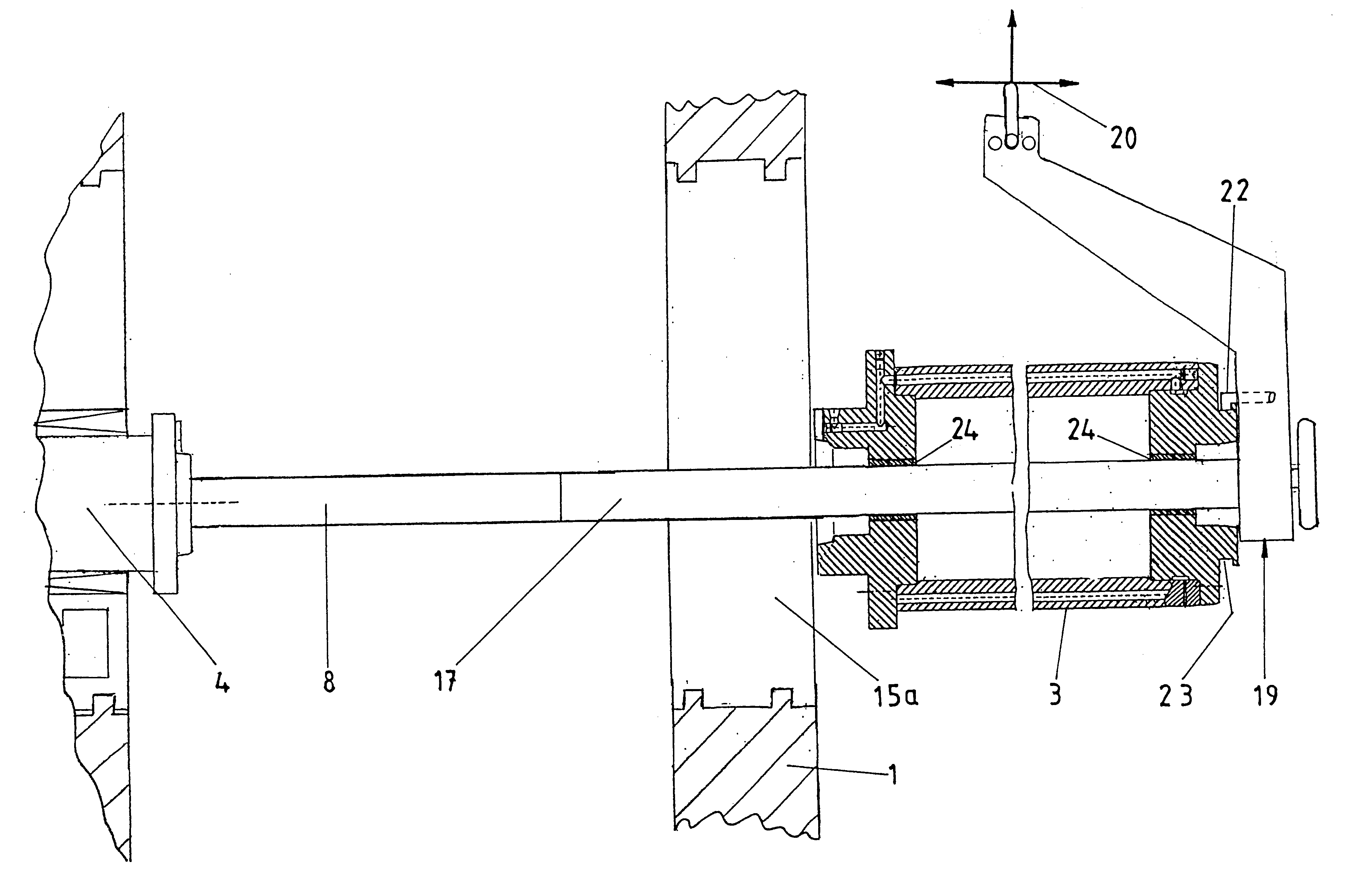
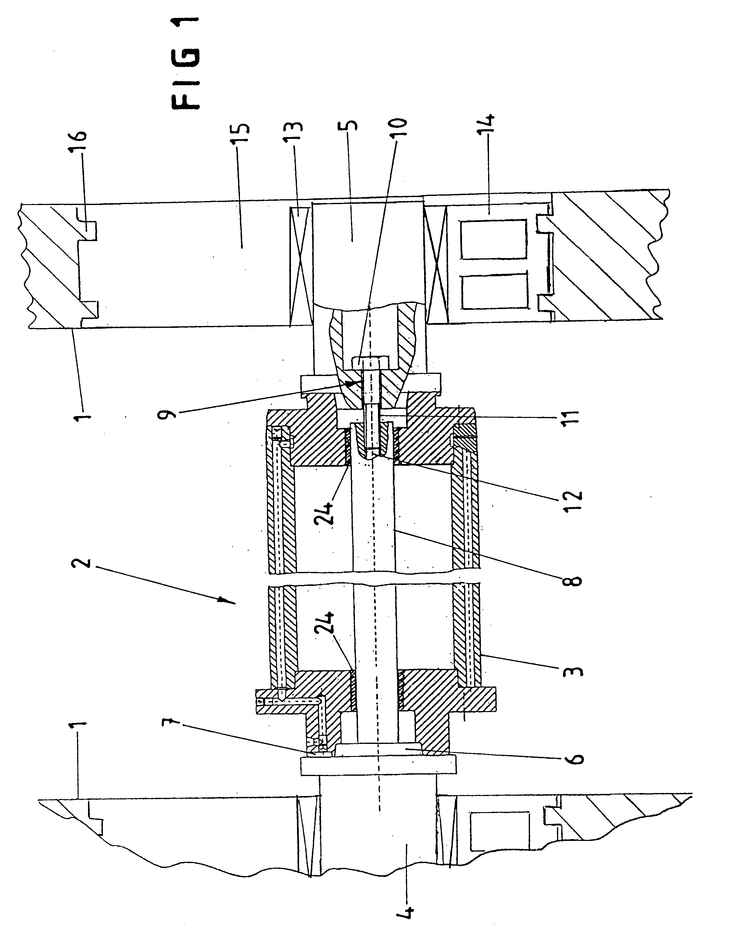
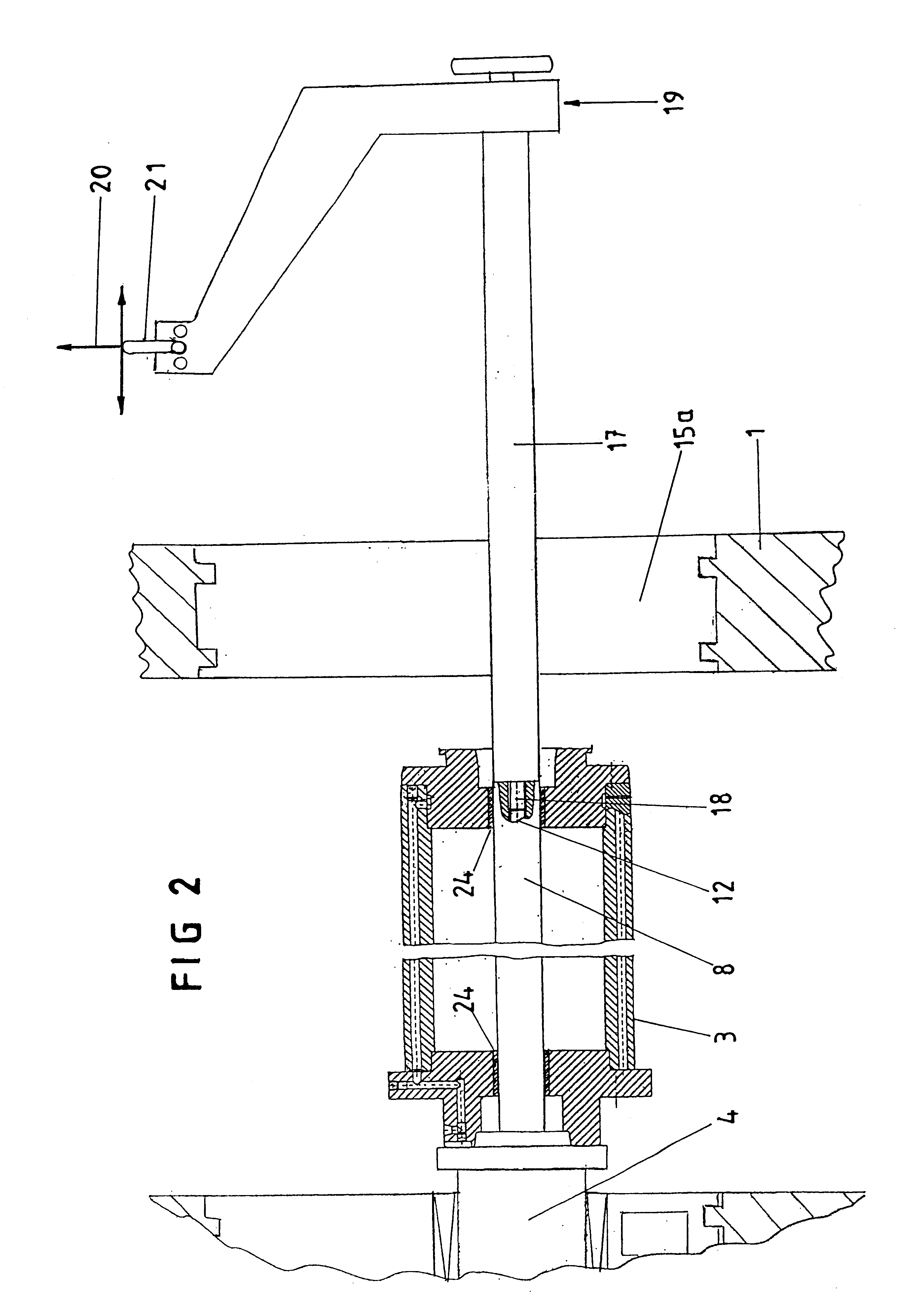
The printing machine, on which FIG. 1 is based and of which only palls of the two side walls and one cylinder 2 are illustrated, contains multi-part cylinders. These each consist of a middle drum 3 and of two lateral bearing stubs 4, 5 receiving the drum 3 releasably between them. During operation, a sleeve, not illustrated in any more detail here, can be received on the drum 3 and is designed as a formed sleeve or transfer sleeve, depending on the type of cylinder. The bearing stubs 4, 5 each possess a cone journal 6 which is assigned a conical scat on the drum side. One of the bearing stubs 4, 5 is connected to a drive device. To transmit the torque to the drum 3, the latter call be screwed to the drive-side bearing stub. In the example illustrated, the drive-side bearing stub 4 is provided with one or more axially projecting drivers 7 which engage in the manner of a toothing into associated drum-side driver recesses.

The two bearing stubs 4, 5 are connected to one another by means...


PUM

PropertyMeasurementUnit
diameteraaaaaaaaaa
gravityaaaaaaaaaa
movementaaaaaaaaaa

Abstract

In the installation and removal of a cylinder of a printing machine, in which the cylinder has a middle drum and two lateral bearing, stubs which are capable of being secured releasably to the drum and of being connected to one another by means of a central spindle which passes through the drum and which at least at one end, can be screwed, by means of a screw connection provided within the outer circumference of the spindle, to the adjacent bearing stub which, with the screw connection released, can be removed, together with its bearing housing, at least to all extent such that the drum is accessible from the side, a high degree of safety and a time saving can be achieved in that, for the change, the drum of a cylinder is released from the bearing stubs and one bearing stub is removed, after which the consequently exposed end of the spindle of the cylinder has connected to it, in the same way as the removable bearing stub, a spindle extension, onto which the drum is pushed and which is then released from the spindle and moved away together with the drum, and vice versa.

Description

1. Field of the InventionThe invention relates to a method for the installation and removal of a cylinder of a printing machine and to a device, suitable for this purpose, for receiving a cylinder of a printing machine.2. Description of the Related ArtA printing machine, in which the cylinder has a middle drum and two lateral bearing stubs which are capable of being secured releasably to the drum and of being connected to one another by means of a central spindle which passes through the drum and which, at least at one end, can be screwed, by means of a screw connection provided within the outer circumference of the spindle, to the adjacent bearing stub which, with the screw connection released, can be removed, together with its bearing housing, at least to an extent such that the drum is accessible from the side, is in the applicant's possession. However, a suitable device for the installation and removal of the cylinders is not available. Hitherto, the procedure. in this case, has...

Claims


Application Information

Patent Timeline
Patent Type & Authority Patents(United States)
IPC IPC(8): B41F13/00B41F13/08B41F13/24B41F13/26
CPCB41F13/00B41F13/08Y10T29/4973Y10T29/49815B41P2227/20
Inventor GOTTLING, JOSEFPETERSEN, GODBER
Owner MANROLANAD AG
Why Eureka
Try Eureka