
Brightness-variation compensation method and coding/decoding apparatus for moving pictures

a compensation method and brightness variable technology, applied in the direction of signal generators with optical-mechanical scanning, color televisions with bandwidth reduction, signal systems, etc., can solve the problems of insufficient improvement of coding efficiency, insufficient quantity, and inability to properly detect movemen

Inactive Publication Date: 2002-09-24
NIPPON TELEGRAPH & TELEPHONE CORP
View PDF2 Cites 457 Cited by
  • Summary
  • Abstract
  • Description
  • Claims
  • Application Information

AI Technical Summary

Benefits of technology

This approach enhances coding efficiency by accurately accounting for overall brightness changes, reducing data quantity and improving coding performance, especially in cases of fade-ins and fade-outs, by using parameters that minimize squared differences between image frames.

Problems solved by technology

(1) The detection of movement is not properly performed.
(2) The coding efficiency is not sufficiently improved.
However, although this resolves problem (1), the size of the interframe luminance difference values can still result in problem (2).
However, since this technique involves sending coded data expressing the luminance change for each small area, the quantities of data are ultimately increased to such a degree that the overall data quantity is not much different.
In other words, the coding efficiency is not much improved.
With this technique, the quantity of coded data is extremely small because it is sufficient to send only a single piece of coded data expressing the luminance change for each image frame.
Therefore, the assumption of Equation (1) does not hold in this case, and the precision is insufficient to express overall luminance changes using only the parameter D.sub.B.
Therefore, the approximation of Equation (1) is insufficient for determining one type of luminance change over the entire image frame.

Method used


Image

  • Brightness-variation compensation method and coding/decoding apparatus for moving pictures
  • Brightness-variation compensation method and coding/decoding apparatus for moving pictures
  • Brightness-variation compensation method and coding/decoding apparatus for moving pictures

Examples


Embodiment Construction

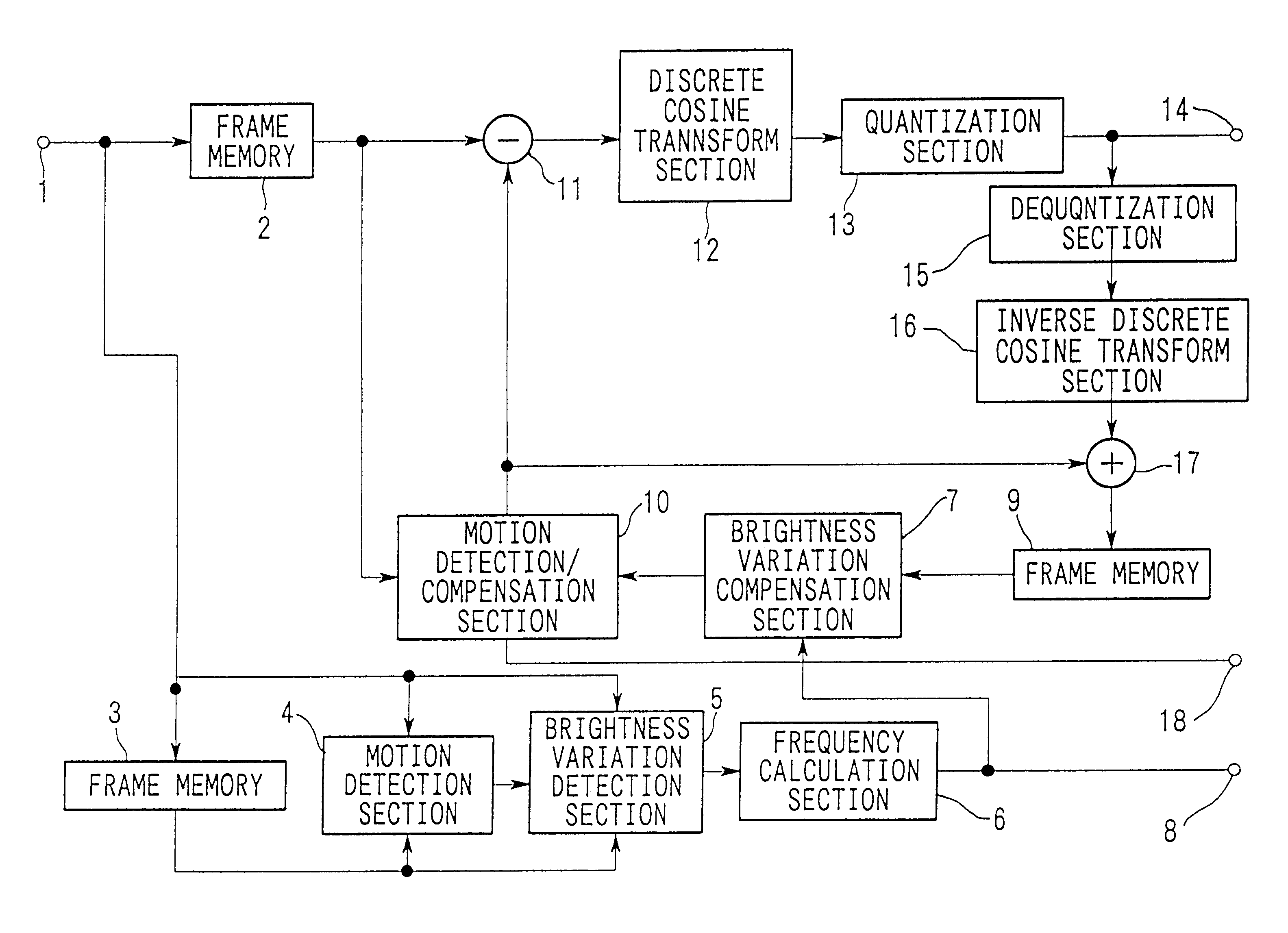
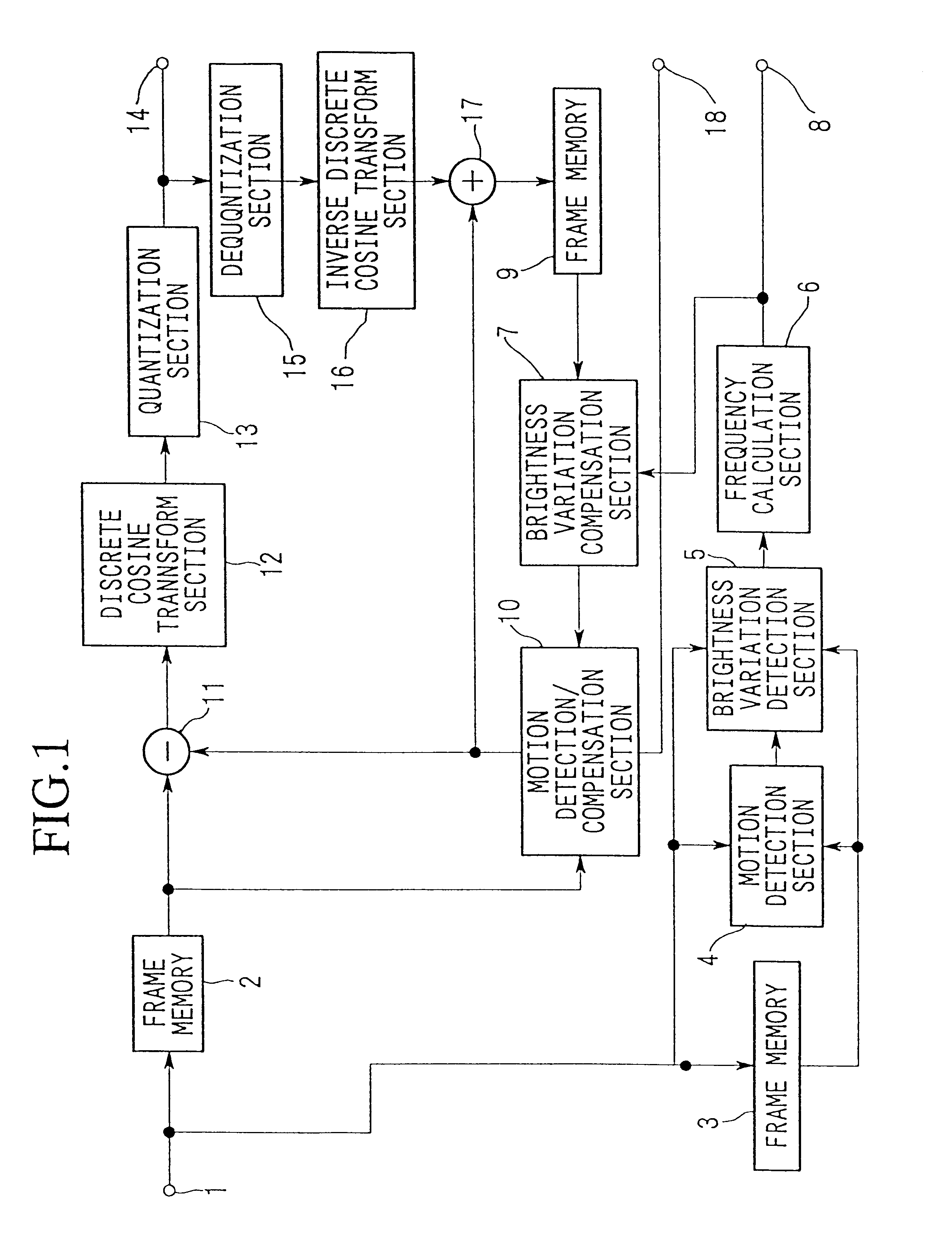
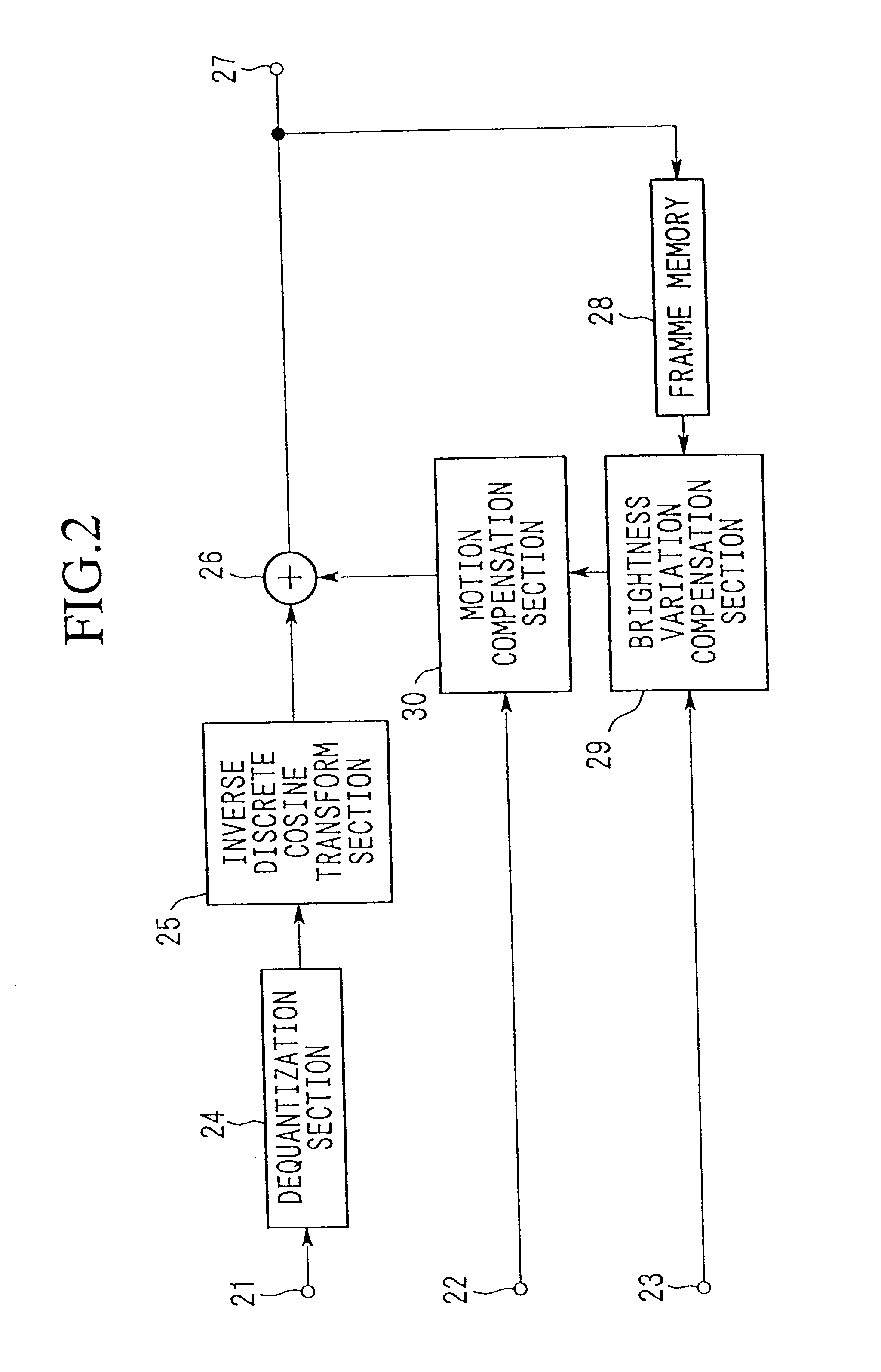
Hereinbelow, a brightness variation compensation method and moving image coding / decoding apparatus according to the present invention shall be explained. Brightness variation compensation of moving images and coding / decoding of moving images using brightness variation compensation are performed by units of image planes. Here, "image plane" is a comprehensive expression referring to an "image frame" corresponding to a single frame of a moving image or a "video object plane" (hereinafter abbreviated to "VOP") which is an image corresponding to the variation over time of the contents of a moving image. Below, an explanation will be made using image frames as examples of image planes. VOPs shall be explained separately later.

First, the brightness variation compensation method for moving images according to the present invention shall be explained.

The brightness variation compensation method of the present invention compensates for overall brightness variations by correcting the luminanc...


PUM


Abstract

A moving image brightness variation compensation method for encoding digital moving images for transmission and storage, and for image processing when editing moving images, the moving image brightness variation compensation method comprising a step of compensating for overall brightness variations by correcting a luminance value x of each pixel according to the formula DC.x+DB, wherein DB is a parameter indicating a gain change and DC is a parameter indicating a contrast change, the parameters representing overall luminance changes between a reference image plane and an image plane being processed.

Description

1. Field of the InventionThe present invention relates to a method of compensating for the overall brightness variation between image frames required for image processing such as in video editing and coding for efficient transmission and storage of digital video images.2. Background ArtAs a conventional coding technique for efficiently transmitting and storing video image data, a technique known as motion compensation interframe prediction coding has been widely used. With this technique, the luminance values (or color differences) of the image frames being processed are not directly transmitted and stored; instead, the technique measures how much objects inside an image have moved between a video image frame which has already been coded (referred to as a reference image frame) and the image frame being processed, and luminance difference values at positions which are shifted by the distance of movement are transmitted and stored.Movement compensation interframe prediction coding en...

Claims


Application Information

Patent Timeline
Patent Type & Authority Patents(United States)
IPC IPC(8): H04N7/50H04N7/26
CPCH04N19/105H04N19/176H04N19/172H04N19/46H04N19/51H04N19/61H04N19/142H04N19/162
Inventor KAMIKURA, KAZUTOWATANABE, HIROSHIJOZAWA, HIROHISA
Owner NIPPON TELEGRAPH & TELEPHONE CORP
Learn More