
Pumpjack dynamometer and method

a dynamometer and push rod technology, applied in the field of push rod dynamometers, can solve the problems of not always providing accurate or reliable information, adversely affecting the reliability of much of the sensing equipment, and being subject to wear and tear, etc., and achieve the effect of long-term calibration errors and high reliability

Inactive Publication Date: 2002-06-25
MILLS MANUEL D
View PDF11 Cites 28 Cited by
  • Summary
  • Abstract
  • Description
  • Claims
  • Application Information

AI Technical Summary

Benefits of technology

It is another object of the present invention to provide a highly reliable device whereby long term calibration errors are at least substantially eliminated so that the dynamometer card changes over time are indicative of changes in the well rather than changes in calibration.
It is yet another object of the present invention to provide an improved data sampling method.

Problems solved by technology

Consistency requires that calibrations remain constant and do not change over time, as has been a problem with many prior art devices.
The problem with such position sensing devices is that they are usually subject to wear, require careful initial calibration, require maintenance including regular re-calibrations, and may not always provide accurate or reliable information.
Hydrogen sulfide gas is often present in the vicinity of the pump jack, and that gas adversely affects the reliability of much of this sensing equipment.
Well personnel working on the pumpjack may inadvertently loosen or change components in such a way that calibrations are affected.
Prior art equipment for sensing the position of a walking beam is frequently mounted on the walking beam at a location where it is highly susceptible to weather conditions such as variable temperature, and may have reduced reliability due to temperature drift errors.
Minor irregularities or mechanical jitters in movement of the walking beam may also cause spurious or repeatable errors.
As the dynamometer data is produced, various means are used to collect and use the data, some of which require expensive sensors, some of which may be less reliable over time, and some of which may require significant maintenance for calibration requirements.
However in some areas, use of radio transmitters is not allowed.
Where radio transmitters are allowed, it is often difficult to obtain additional channels for transmission.
As well, FCC rules must be followed and may require radio transmitters to be installed according to certain specifications that may limit their usefulness for some purposes.
Infrared transmitters have limited usefulness in sunlight due to ambient infrared noise that results in a short transmission distance if operation is possible at all.
As well, infrared transmitters have limited selectivity and would have problems for use with closely spaced wells where multiple transmissions may occur.
Although the above-listed patents address problems relating to position indicating sensors, they do not disclose highly reliable techniques for automatic calibration and re-calibration of such devices to thereby substantially eliminate calibration errors that may otherwise distort dynamometer cards taken at different times using prior art devices.

Method used


Image

  • Pumpjack dynamometer and method
  • Pumpjack dynamometer and method
  • Pumpjack dynamometer and method

Examples


Embodiment Construction

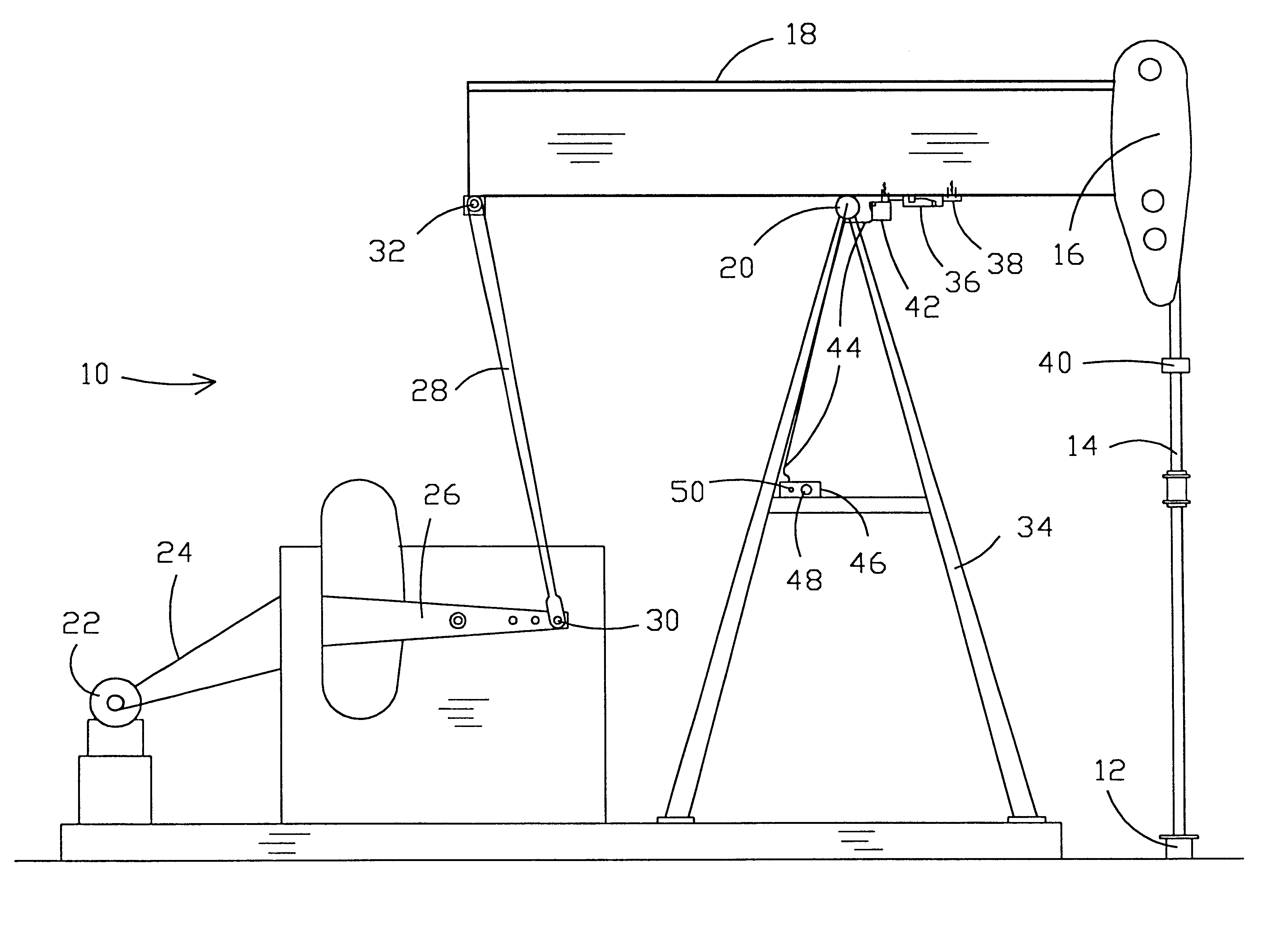
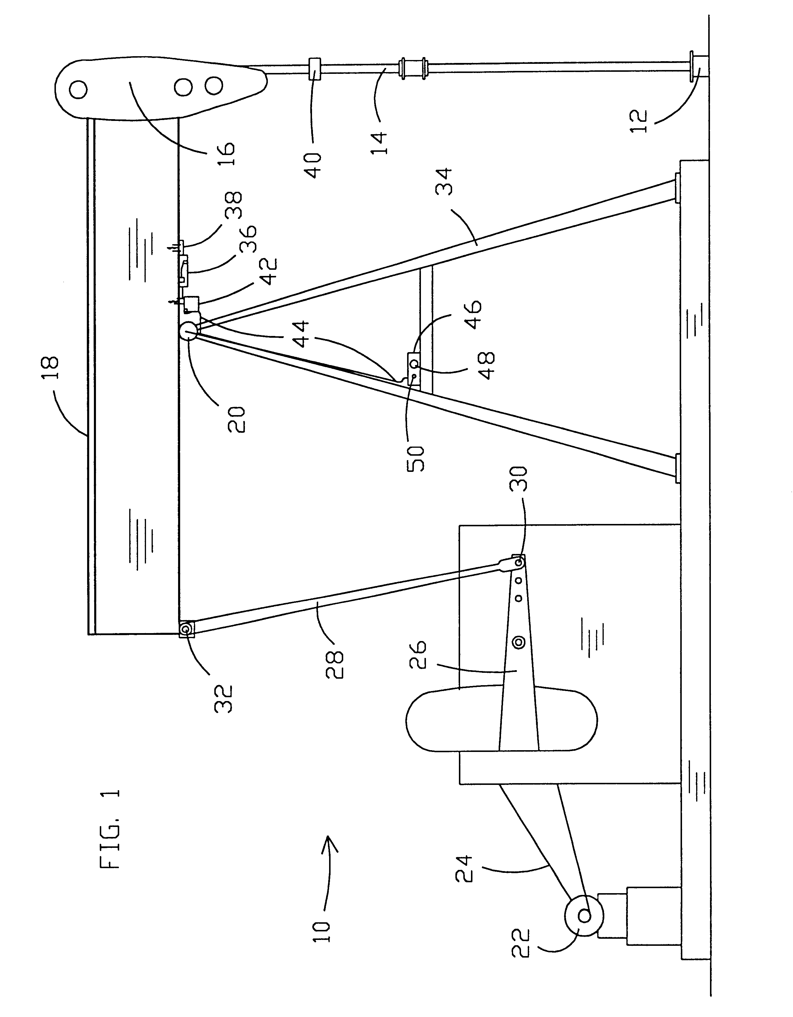
Referring now to the drawings, and more particularly to FIG. 1, a pumpjack unit 10 is shown in operative relationship respective to a wellhead 12. A downhole pump (not shown) is activated by reciprocal movement of sucker rod string (not shown) and polished rod 14 that is suspended from horse head 16. Horse head 16 is affixed to walking beam 18, which is a rigid beam that extends on either side of pivot connection 20. Walking beam 18 is reciprocated by a prime mover 22, which may typically comprise an electric motor. Prime mover 22 drives walking beam 18 through a drive system which may typically comprise elements such as drive belt 24, crank arm 26, drive arm 28 that is pivotally connected to walking beam 18 and crank arm 26 with pin connections 30 and 32. Walking beam 18 is pivotally supported by a suitable frame 34 such that walking beam pivots in two different directions, moving sucker rod string and polished rod 14 upwardly and downwardly during each pump stroke.

A load transduce...


PUM


Abstract

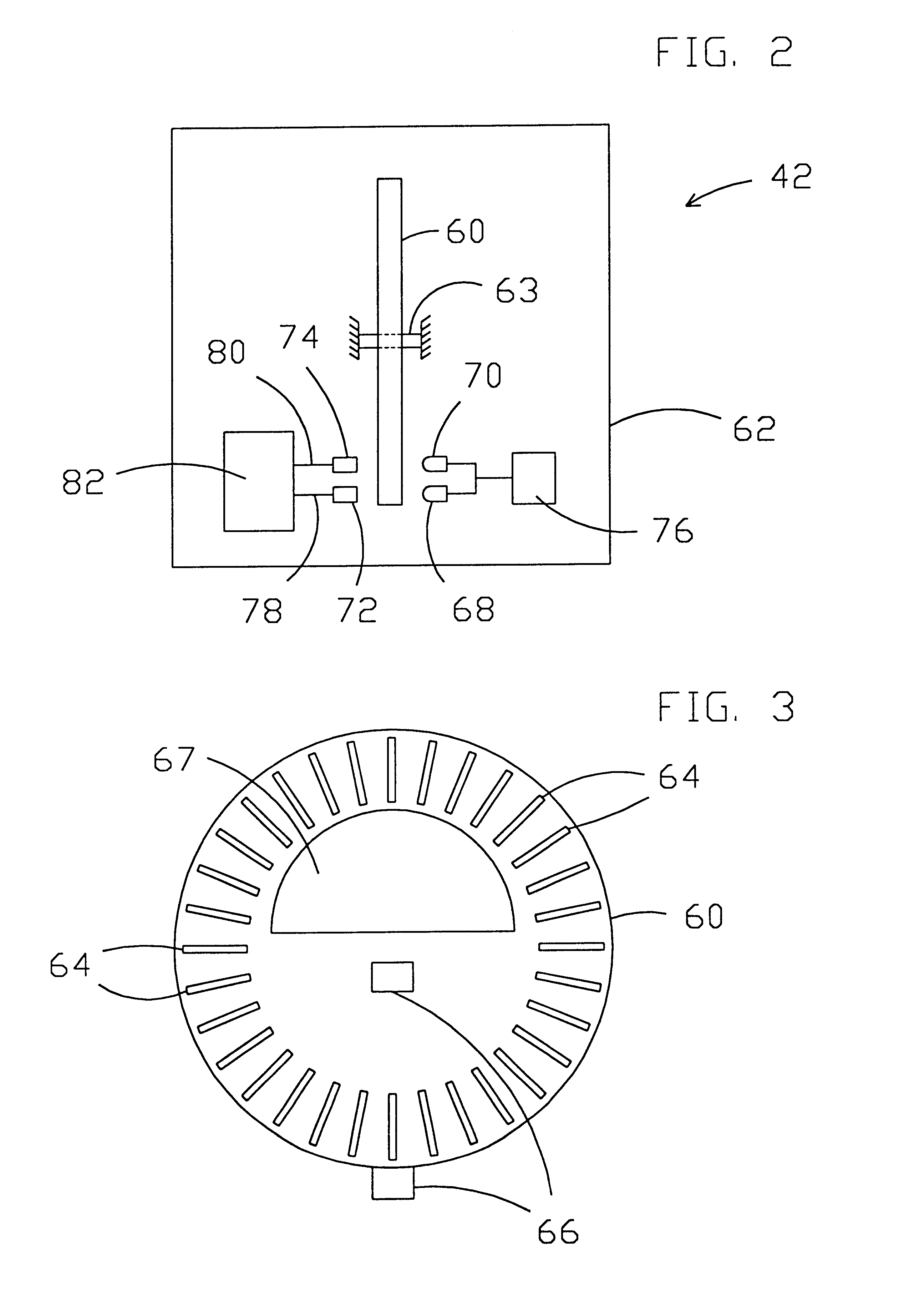
A dynamometer readout (42, 46) and method is disclosed for obtaining dynamometer information (110) related to pumpjacks (10). For this purpose, a change of pivotal direction of the walking beam (18) may be detected by processor (82) utilizing an encoder component (60) with spaced slots (64) therein and light signal devices (68, 70, 72, 74) positioned to have a spacing different from that of the spacing of the slots (64). Software techniques filter out effects of stray mechanical vibrations. An infrared transceiver (46, 50, 100) of a preferred embodiment includes a radio frequency carrier generator (90) and modulator (88) that produces an infrared signal receivable by a low cost consumer radio receiver. The radio frequency modulation technique for infrared signals (96) and related filtering (98, 102, 104) condition formatted infrared signals for utilization in daylight and through a car window for drive-by downloading of data to second computer (108). A sensor (163) may be substituted for the encoder. A sensor (163) may include a moveable light interrupter, such as a ball (160) or a bubble (260), moveably disposed within the sensor. The sensor may also provide one or more apertures (180) for transmitting light through the apertures.

Description

1. FIELD OF THE INVENTIONThe present invention generally relates to pumpjack dynamometers and, more particularly, to apparatus and methods for producing and transmitting dynamometer card information.2. BACKGROUND OF THE INVENTIONDynamometers are commonly utilized in the oil field to monitor the operation of pumpjacks used to pump oil to the surface. The dynamometer card provides information related to pumping conditions as described in detail in subsequently listed patents. For instance, a typical use of such information involves determining when a well has reached what is known as a "pump-off" condition wherein the wellbore does not receive enough oil to fill the downhole pump during the entire pump stroke. Changes in the dynamometer card readings over time may be used to provide this information. It may be desirable to temporarily stop operating the pump until the pump off condition has been obviated by continued flow from the formation into the wellbore while the pump is shut dow...

Claims


Application Information

Patent Timeline
Patent Type & Authority Patents(United States)
IPC IPC(8): F04B49/06F04B47/02E21B47/00F04B47/00
CPCE21B47/007E21B47/009F04B47/022F04B49/065
Inventor MILLS, MANUEL D.
Owner MILLS MANUEL D
Learn More