
Controllable filter

a controllable filter and filter technology, applied in the direction of multiple-port active networks, multiple-port electrical equipment, multiple-port networks, etc., can solve the problems of interference that cannot be informed, the fixed part of the cordless telephone system cannot be informed, and the interference of the traffic on the cellular network

Inactive Publication Date: 2002-04-30
TELEFON AB LM ERICSSON (PUBL)
View PDF6 Cites 5 Cited by
  • Summary
  • Abstract
  • Description
  • Claims
  • Application Information

AI Technical Summary

Benefits of technology

It is the object of the present invention to provide a device for enabling the above described type of communication, which at the same time is low in cost and efficient.
It should be noted that the above described filter device is not restricted to being applied in the fixed part of a cordless telephone system. Much rather, the application to any communication system that may advantageously employ the above mentioned simplex listening operation is possible. For example, another advantageous application of the controllable filter of the present invention is in mobile hand-sets that function in accordance with any given mobile standard, where the use of the filter of the invention as a front-end filter allows the providing of a walkie-talkie function, i.e. two hand-sets may directly communicate with one another without the intervention of the cellular system. This is again achieved by not adding a second receiver and second transmitter to the mobile station, but by letting the mobile station aquire receiving and transmission capability in one common band, for instance by a second receiving path in the uplink band.

Problems solved by technology

This conventional approach, however, has a problem in that interference can nonetheless occur, namely if a rearrangement of the cellular frequencies takes place while there is no mobile station logged on to the cordless telephone system, and consequently the fixed part of said cordless telephone system cannot be informed of the rearrangement.
In this case, the fixed part will continue to transmit on the same beacon channel (which is the CTS equivalent of the broadcast control channel BCCH in GSM) and thereby possibly interfere with the traffic on the cellular network.

Method used


Image

  • Controllable filter
  • Controllable filter
  • Controllable filter

Examples


first embodiment

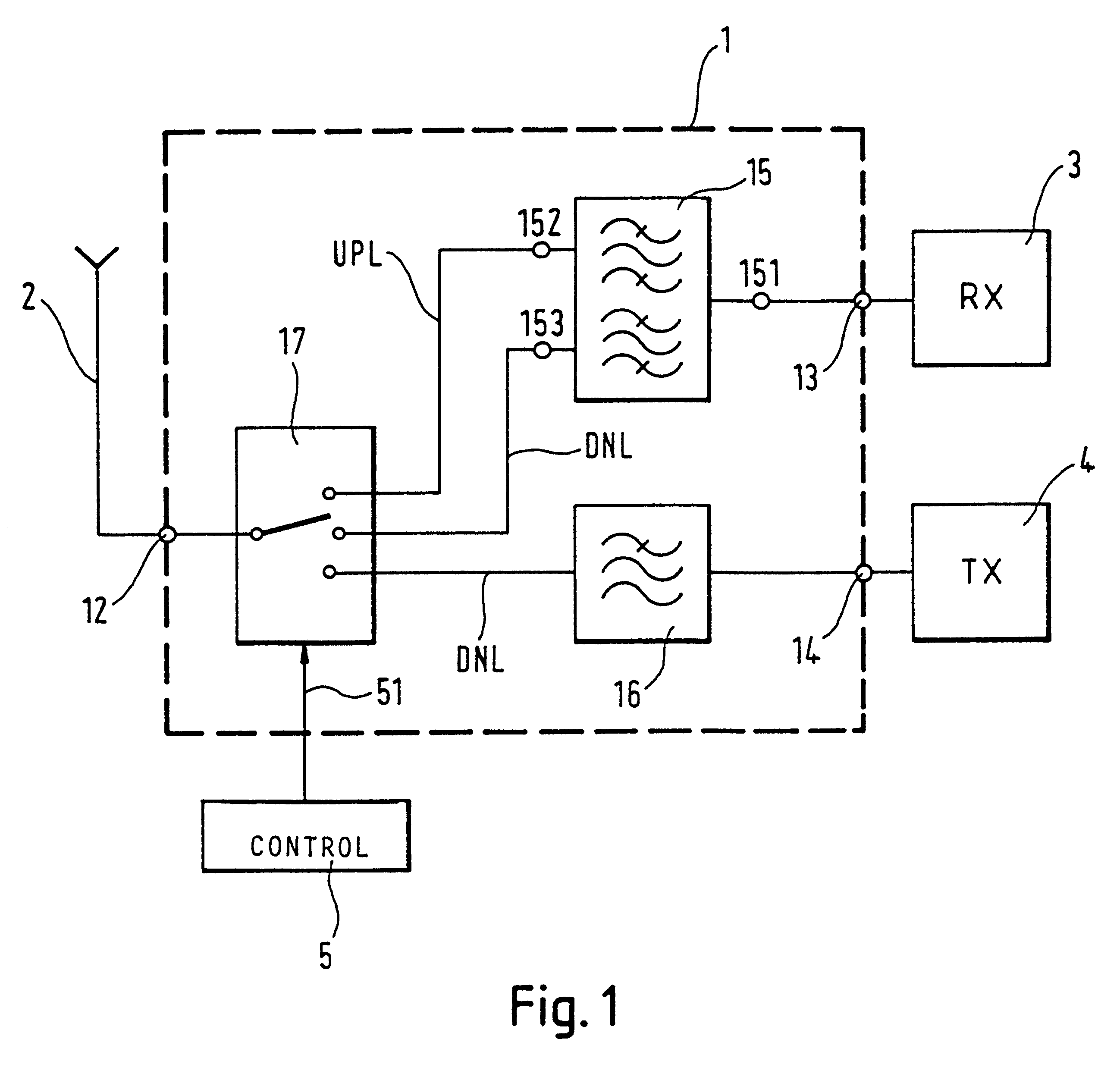
the present invention is shown in FIG. 1. Elements that correspond to those already shown in FIG. 8 carry the same reference numeral and shall not be described again. As can be seen, the first embodiment uses a controllable switching means 17 for splitting the antenna connection 12 into three branches, and uses a duplex filter 15 for re-combining the two branches that relate to reception, i.e. an up-link reception branch and a down-link reception branch. Moreover, a filter 16 is provided, for producing the desired filter characteristic between the antenna terminal 12 and the transmitter terminal 14 of the controllable filter 1.

Preferably, the filter characteristic of filter 16 is such that it overlaps with the filter characteristic in the downlink branch leading to the receiver 3, i.e. the filter characteristic between terminals 151 and 153 of duplex filter 15. Examples for the different characteristics in the case of a dual-mode cordless and cellular system in accordance with GSM a...

second embodiment

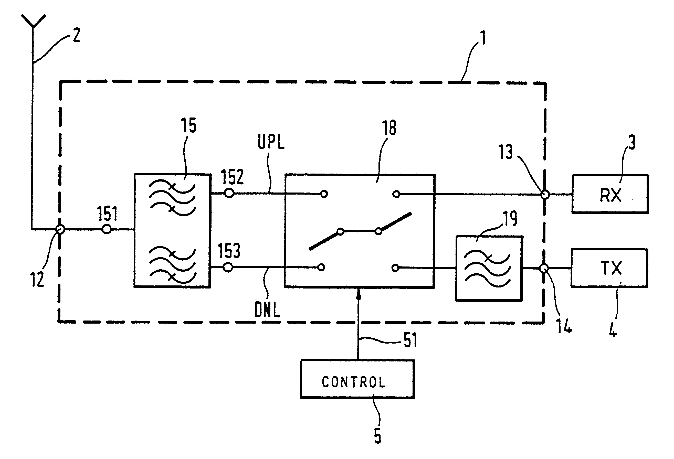
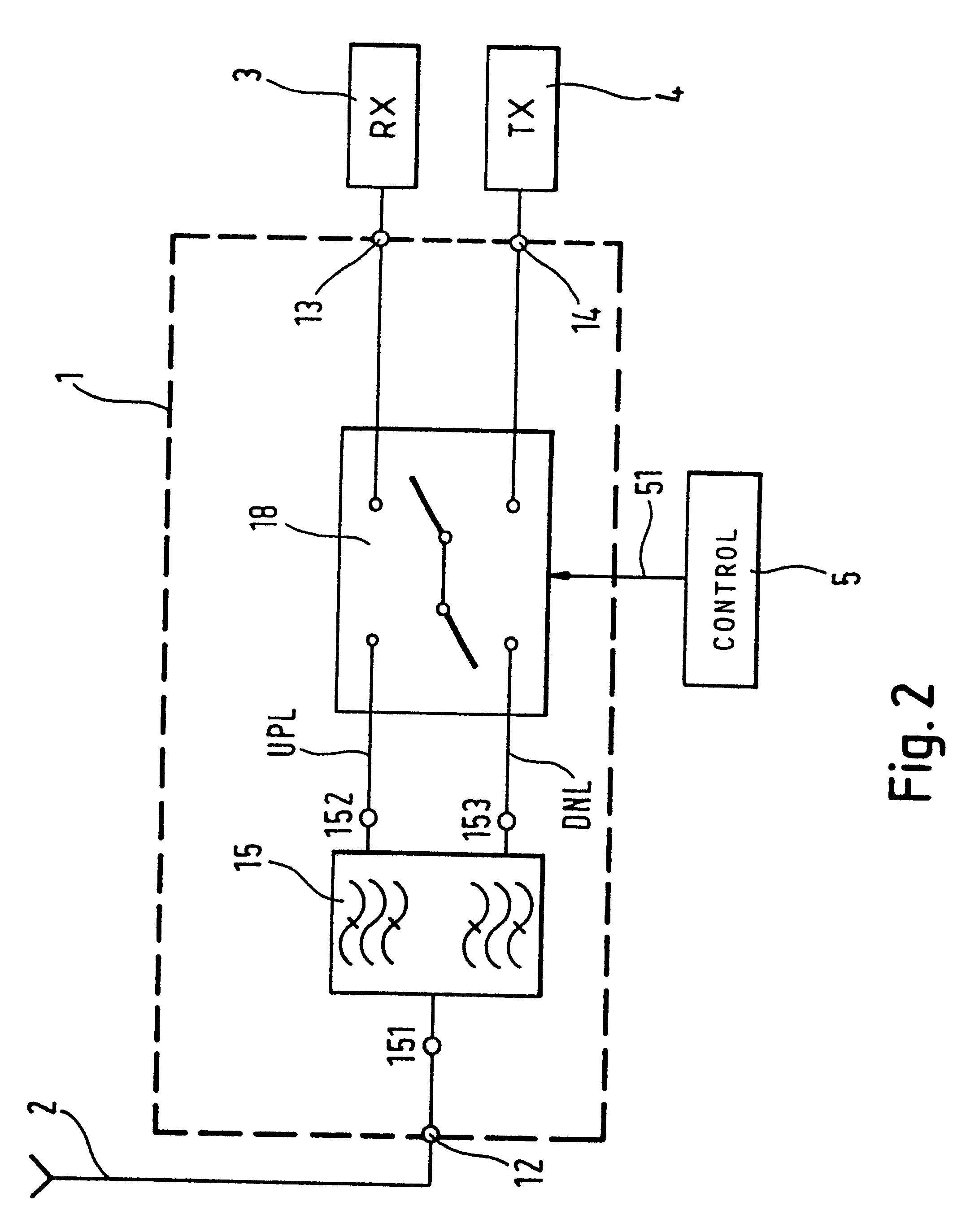
the present invention is shown in FIG. 2. Elements already described in connection with FIGS. 1 and 8 carry the same reference numerals and shall not be described again. As can be seen from FIG. 2, the difference to the first embodiment shown in FIG. 1 lies in the fact that the duplex filter 15 is now provided at the antenna terminal 12 of the filter 1. Also, a switching means 18 is provided, that acts as both an up-link / down-link and a transmitter / receiver switch.

In order to better explain the operation of the circuit shown in FIG. 2, it is assumed that the shown filter is being used in the fixed part of a cordless telephone system, and that therefore an up-link receiver branch, down-link receiver branch and a down-link transmitter branch need to be provided. In this connection it may already be noted that in the event of employing the filter in a mobile station in order to provide walkie-talkie features, the references "uplink" and "down-link" in FIGS. 1, 2 and 3 would simply have...


PUM


Abstract

The application relates to a controllable filter (1) that is placed between an antenna on the one side and a receiver and transmitter on the other, where the receiver branch can be switched between two filter characteristics. In this way, a simple device for allowing simplex reception in the transmission band can be provided. This filter is preferably applied as a frontend filter (FP) in the fixed part of a cordless telephone system and / or in a mobile station to thereby provide said mobile station with walkie-talkie capabilities.

Description

The present invention relates to a controllable filter for being interposed between an antenna on the one side and a receiver and a transmitter on the other side, such as a frontend filter for a communication device, for example a radio telephone apparatus.Recently, telephone systems that combine cellular telephone capabilities and cordless telephone capabilities have been proposed. Such an arrangement is schematically shown in FIG. 5. As can be seen in FIG. 5, the cordless telephone system (CTS) consists of a so-called fixed part FP and a mobile hand-set MS. Communication between the fixed part PP and the mobile hand-set is conducted along an uplink band, which is associated with the transmitter TX of the mobile part and the receiver RX of the fixed part. Equally, a down-link band is provided, which is distinct from the up-link band, with which the transmitter TX of the fixed part FP and the receiver RX of the mobile part is associated.Furthermore, the mobile part MS can also commu...

Claims


Application Information

Patent Timeline
Patent Type & Authority Patents(United States)
IPC IPC(8): H03H11/02H03H7/00H03H11/34H03H7/46
CPCH03H7/465
Inventor MEIXNER, MICHAEL
Owner TELEFON AB LM ERICSSON (PUBL)
Learn More