
Shaped information coding device for interlaced scanning video and method therefor

a technology of information coding and interlaced scanning, which is applied in the field of shape information coding device for interlaced scanning video and the method therefor, can solve the problems of reducing coding efficiency, large number of shape information coding bits generated, and serious video shape change between the two fields

Inactive Publication Date: 2002-04-30
PANTECH CO LTD
View PDF8 Cites 124 Cited by
  • Summary
  • Abstract
  • Description
  • Claims
  • Application Information

AI Technical Summary

Problems solved by technology

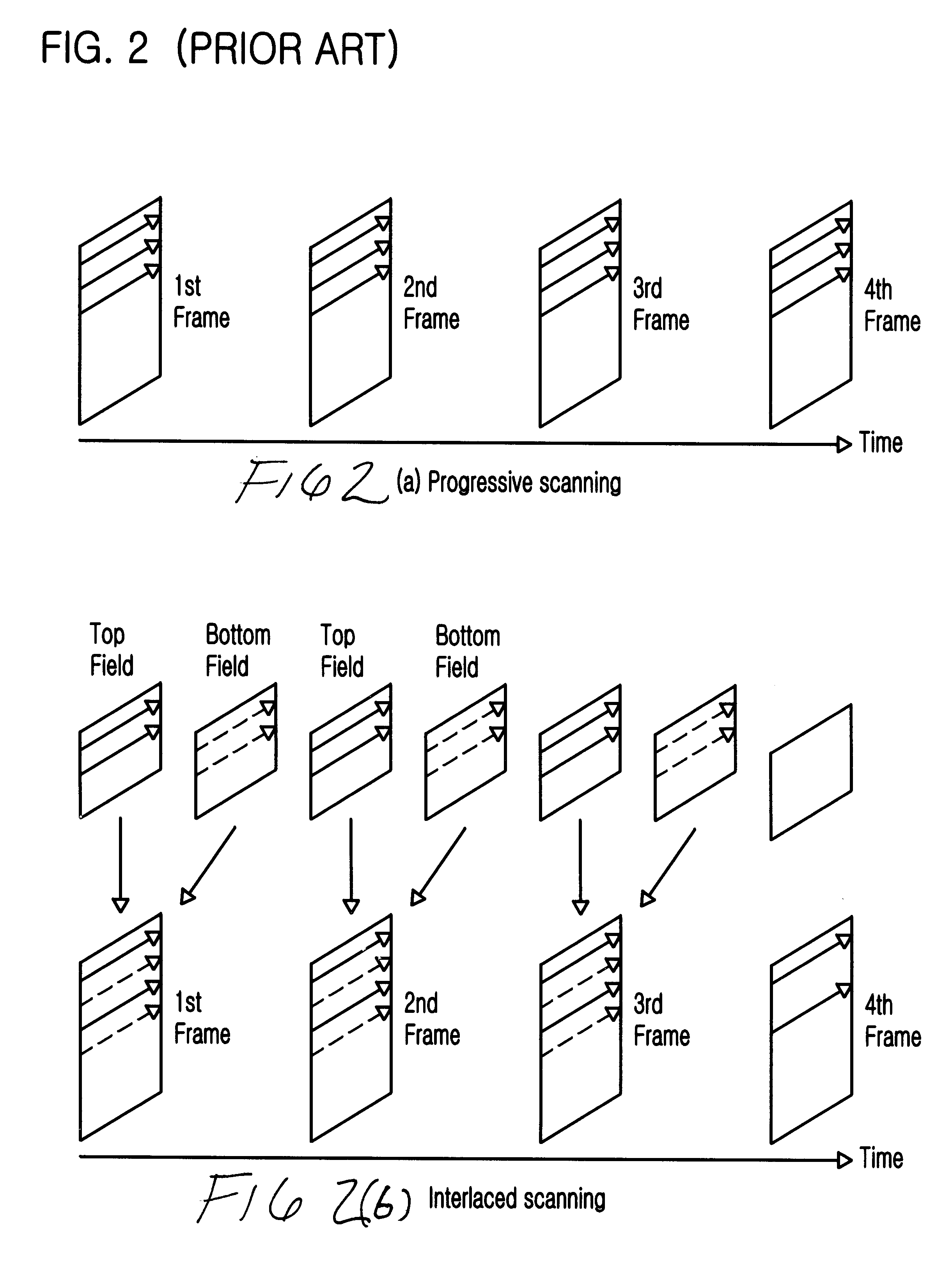
Meanwhile, in case of the interlaced scanning video, since one frame is divided into two fields, the shape is formed in a complicated manner, as shown in FIG. 8A, to thereby decrease the coding efficiency, if the frame BAB is coded in the BAB unit.
Change of the video shape between the two fields is serious because time variation is great.
In the case where the size of motion between the two fields is large, if the conventional frame coding method is embodied, there occurs a problem that a large number of the shape information coding bits are generated.
However, the conventional MVPs determining method as mentioned above does not reflect the characteristic of the interlacing scanning video.

Method used


Image

  • Shaped information coding device for interlaced scanning video and method therefor
  • Shaped information coding device for interlaced scanning video and method therefor
  • Shaped information coding device for interlaced scanning video and method therefor

Examples


Embodiment Construction

Reference will now be made in detail to the preferred embodiments of the present invention, examples of which are illustrated in the accompanying drawings.

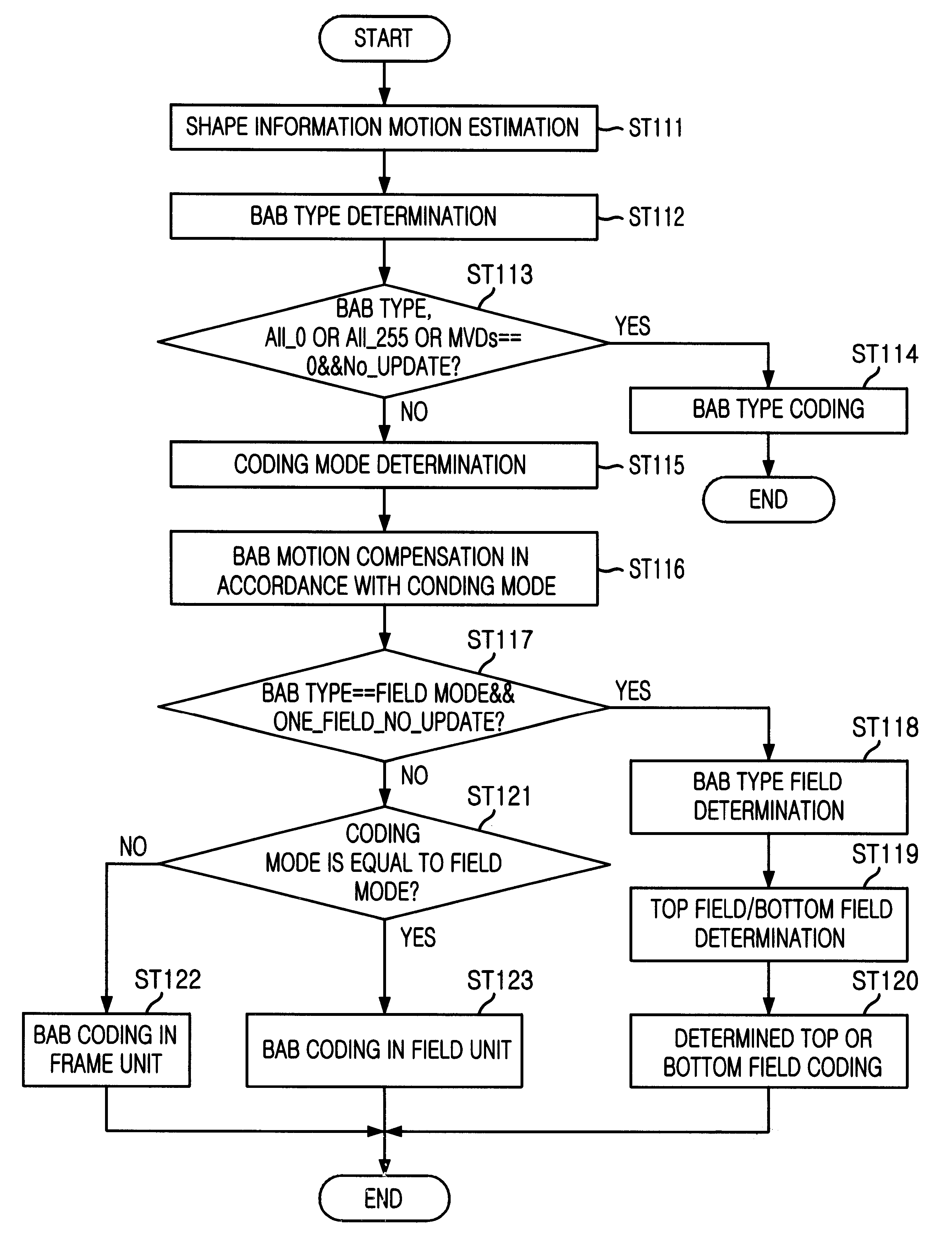
Now, the construction and operation of a shape information coding device for interlaced scanning video according to a preferred embodiment of the present invention will be discussed hereinafter. In case of interlaced scanning video, coding efficiency is varied in accordance with an amount of motion. In the preferred embodiment of the present invention, a frame BAB and a field BAB are adaptively divided from each other and are then coded, thus to achieve an optimal coding efficiency.

FIG. 9 is a flow chart illustrating a shape information coding method for interlaced scanning video according to the present invention. In the present invention, the coding of shape information is executed not in a whole video unit, but in a BAB unit, as shown in FIG. 9. In this figure, an input is the BAB, and the steps shown in FIG. 9 as many as the n...


PUM


Abstract

Shape information coding device for interlaced scanning video and method in which the shape information coding device and method can detect an amount of motion of object video, on coding of interlaced scanning video, select field or frame coding mode in accordance with the detected result, perform motion compensation in a field unit if the selected coding mode is the field mode, and perform motion compensation in a frame unit if the selected coding mode is the frame mode. In addition, the present invention can construct one frame with two fields, upon coding of shape information for the interlaced scanning video, and then determine a motion vector predictor for shape by using motion information of adjacent block so as to perform an effective coding of the shape information motion information. At this time, the coding efficiency can be improved by a method contemplating preceding a motion vector having the same motion prediction mode as the current motion vector for the motion vector predictor for shape having a high similarity and determining the motion vector predictor for shape and by a method contemplating performing coding of the field block type information and the filed discrimination information for one field of the two fields.

Description

1. Field of the InventionThe present invention relates to a shape information coding device for interlaced scanning video and method therefor, and more particularly, to a shape information coding device for interlaced scanning video and method therefor which can detect an amount of motion of object video, on coding of interlaced scanning video and encode the object video in a frame type block unit or in a field type block unit in accordance with the detected result.2. Discussion of Related ArtWith the recent development of the research of next generation video / audio coding technology and system construction, improved effort is tried for video / audio applications which have not been supported by the well known standard plans such as, for example, H.263 and H.261 of ITU-T, and MPEG-1 and MPEG-2 of ISO / IEC. Examples of the accomplished functions are object-based interactive functionality and object-based manipulation. To provide various kinds of new functions, shape information should b...

Claims


Application Information

Patent Timeline
IPC IPC(8): G06T9/00H04N7/26H04N7/36
CPCG06T9/004G06T9/20H04N19/21H04N19/51H04N19/112H04N19/105H04N19/139
Inventor CHUN, SUNG MOONSHIN, DONG KYOOMOOM, JOO HEELEE, JIN HAK
Owner PANTECH CO LTD
Learn More