
Detachable balloon embolization device and method

a balloon and embolization technology, applied in the field of vascular occlusion devices, can solve the problems of insufficient filling of aneurysms, increased difficulty in procedures, and increased risk of impairmen

Inactive Publication Date: 2002-04-30
CODMAN & SHURTLEFF INC
View PDF13 Cites 177 Cited by
  • Summary
  • Abstract
  • Description
  • Claims
  • Application Information

AI Technical Summary

Benefits of technology

The balloon assembly also includes a valve assembly. The valve assembly extends through the wall of the outer balloon and an adjacent,portion of the wall of the inner balloon. The valve assembly has a passageway therethrough and a valve means disposed in the passageway. The distal end of the outer and inner tubular members of the catheter extending into the passageway, and the valve means is operative to permit the passage of the catheter through the valve assembly but preventing the flow of fluid through said valve assembly when the catheter is withdrawn from said valve assembly.
In accordance with still another aspect of the present invention, there is a method for occluding an aneurysm by the use of an occlusion device comprising a balloon assembly which includes an outer balloon, an inner balloon, and a valve assembly. The outer balloon is formed from a porous material and the inner balloon is disposed within the outer balloon. The valve assembly extends through a wall of the inner balloon and an adjacent wall of the outer balloon. A catheter has its distal end removably disposed within the valve assembly. The method comprises the steps of: positioning the balloon assembly within an aneurysm; inflating the inner balloon such that the inner balloon makes contact with the outer balloon to thereby force the outer balloon into contact with the aneurysm; introducing an adhesive material into a region between the inner balloon and the outer balloon thereby causing the inner balloon to become bonded to the outer balloon; perfusing the adhesive material through the porous material of the outer balloon thereby causing the outer balloon to become bonded to the aneurysm; deflating the inner balloon thereby causing the outer balloon to contract which, in turn, reduces the size of the aneurysm; and, detaching the catheter from the balloon assembly thereby causing the valve assembly to close and thereby causing the inner balloon to remain in a deflated state.

Problems solved by technology

Such procedures prove more challenging and carry a greater risk of impairment due to collateral damage when the aneurysm occurs in sensitive areas of the body, such as the brain.
Filling an aneurysm is not always an adequate solution, however.
In some cases, the size of the aneurysm interferes with the surrounding tissue or other blood vessels.
Therefore, the prior art does not always produce adequate results.

Method used


Image

  • Detachable balloon embolization device and method
  • Detachable balloon embolization device and method
  • Detachable balloon embolization device and method

Examples


Embodiment Construction

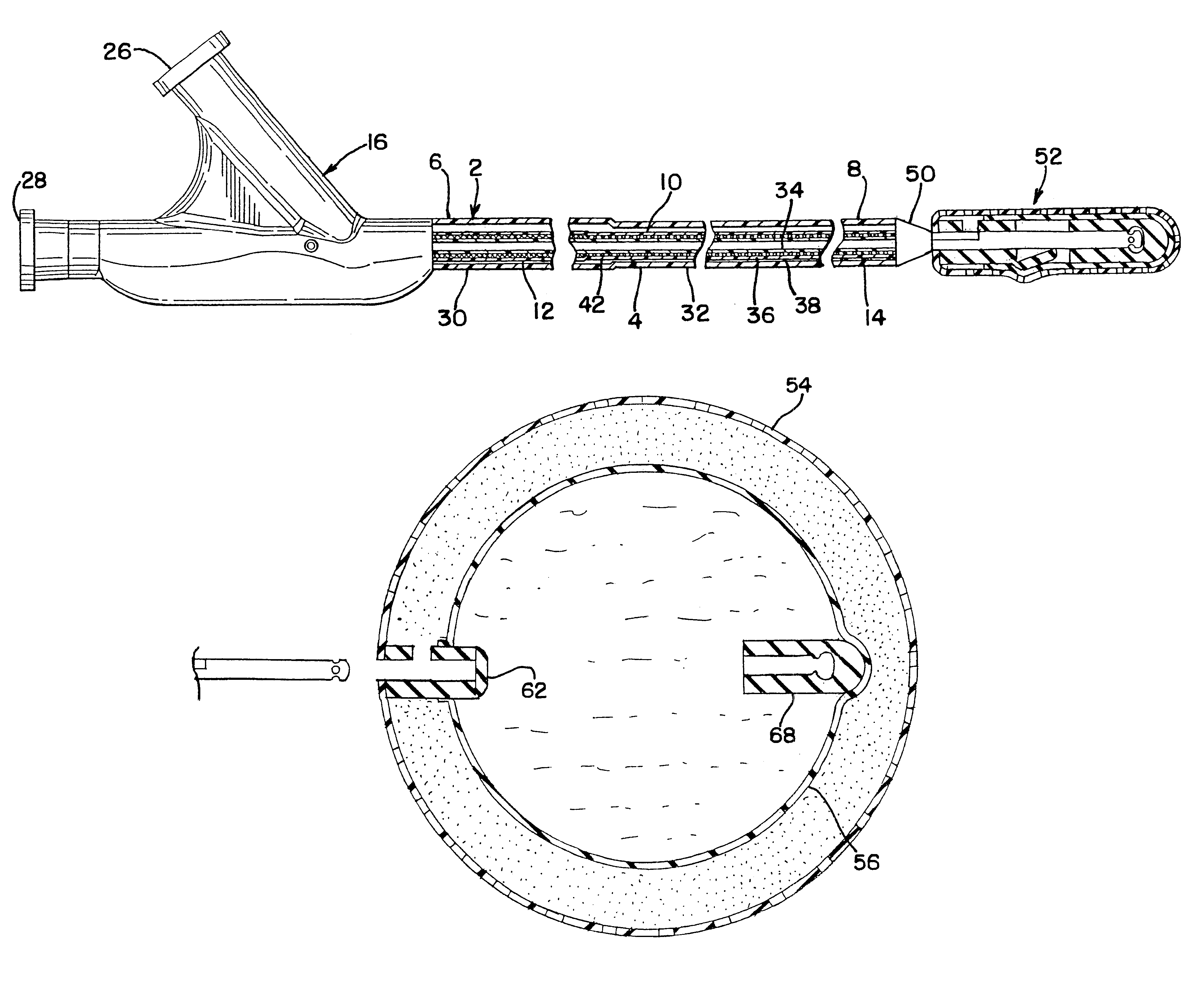
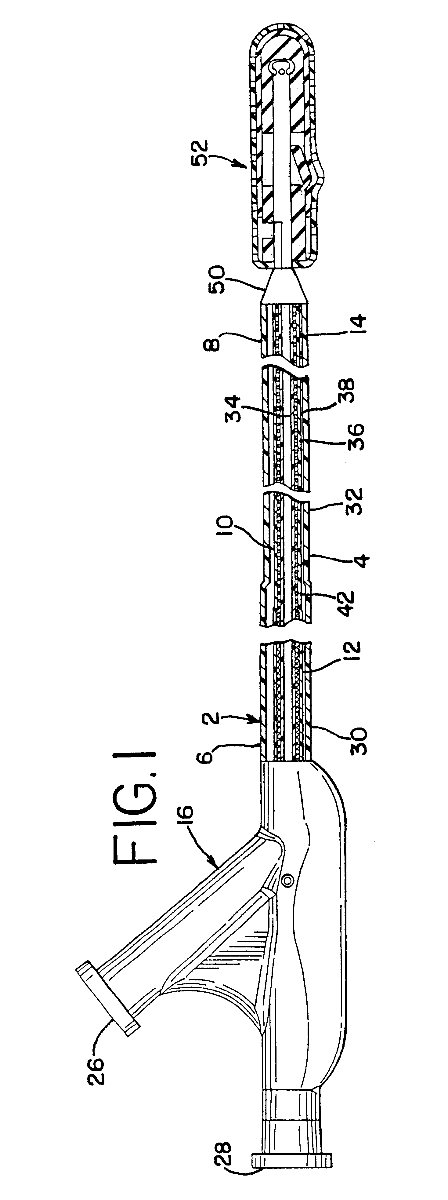
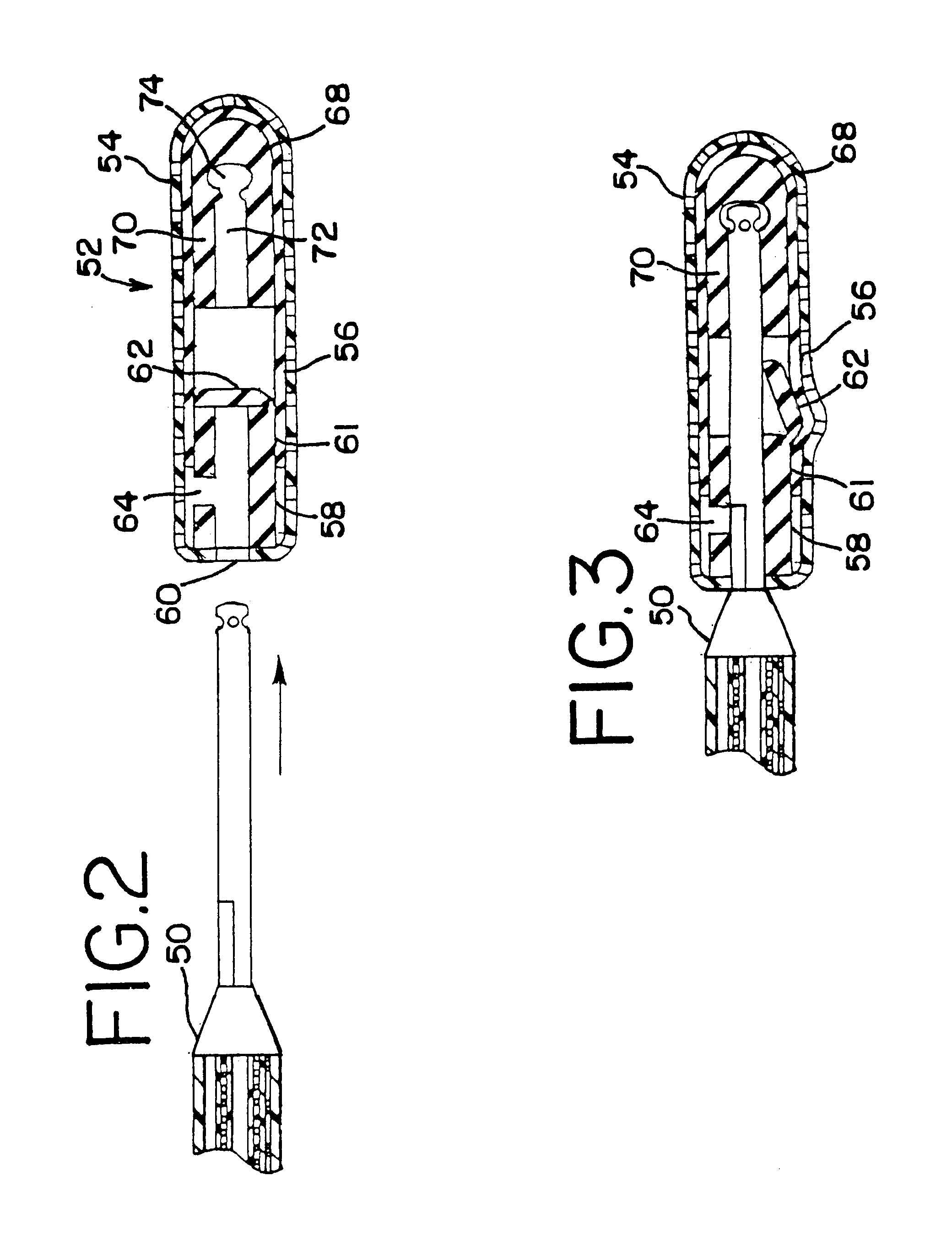
Turning now to the drawings, FIG. 1 illustrates a partial section view of a catheter with a detachable balloon embolization device made in accordance with the present invention. The catheter 2 includes an outer tubular member 4, having a proximal end 6 and a distal end 8, and an inner tubular member 10, having a proximal end 12 and a distal end 14. A dual port Y-connector 16 is coupled to the proximal end 6 of the outer tubular member 4 and the proximal end 12 of the inner tubular member 10. The distal end 8 of the outer tubular member 4 and the distal end 14 of the inner tubular member 10 are adapted using a catheter adapter 50 to attach to a detachable balloon embolization device or balloon assembly 52, the details of which are described below.

As illustrated, the outer tubular member 4 includes a proximal portion 30 and a distal portion 32 of differing diameters, with the proximal portion being larger than the distal portion. In addition, the proximal portion 30 is formed from nyl...


PUM


Abstract

An endovascular aneurysm occlusion device comprising a detachable balloon assembly. The balloon assembly is comprised of an outer balloon and an inner balloon. The outer balloon is formed from a porous material. The occlusion device is expanded within an aneurysm and adhesive material is injected into and perfused through the outer balloon. The adhesive material forms a bond between the aneurysm, the outer balloon, and the inner balloon. The inner balloon is then deflated, which acts to reduce the size of the aneurysm.

Description

1. Field of the InventionThis invention relates generally to vascular occlusion devices and particularly to a vascular occlusion device which is used to reduce the size of an aneurysm.2. Description of the Prior ArtA number of techniques have been developed for the treatment of aneurysms. Initially, aneurysms were treated by invasive surgical methods. A physician would need to surgically remove the aneurysm from the parent vessel. Such procedures prove more challenging and carry a greater risk of impairment due to collateral damage when the aneurysm occurs in sensitive areas of the body, such as the brain.Less invasive techniques have been developed. These techniques involve filling the aneurysm with material to prevent the aneurysm from growing in size. The aneurysm may be filled with a variety of structures, such as coils or balloons. Frequently, the structures used to fill an aneurysm are coated with a thrombogenic material, such as in U.S. Pat. No. 4,638,803 to Rand.Polymers hav...

Claims


Application Information

Patent Timeline
IPC IPC(8): A61B17/12A61M25/12
CPCA61B17/12113A61B17/12136A61M2025/1054A61B2017/1205
Inventor NAGLREITER, BRETT E.JONES, DONALD K.
Owner CODMAN & SHURTLEFF INC
Learn More