Method and device for induction sealing

Inactive Publication Date: 2002-03-26
ALFELDER KUNSTWERKE HERM MEYER
View PDF26 Cites 14 Cited by
  • Summary
  • Abstract
  • Description
  • Claims
  • Application Information

AI Technical Summary

Benefits of technology

This object is achieved for a sealing device for sealing non-circular, in particular polygonal, such as tetragonal, hexagonal, octagonal or elliptical, container orifices, wherein one or more induction loops are provided for sealing and the induction loops are adapted to the shape of the edge of the seal, in that the induction loops are dimensioned in such a way that a homogeneous field adapted to the measurements of the edge of the seal results in sealing, means are provided for controlling the induction loops with respect to the movement of the containers, parallel in time or speed, or means are provided for creating a balance of the production rate of the containers during sealing with respect to the induction loops and means are provided for timing the belts conveying the containers and the pressing and sealing process and for a possible adjustment of pressure during the sealing process.

Problems solved by technology

It is in fact found that the sealing of angular tins proves to be more difficult than the sealing of round tins.
These glass containers are, however, not suitable for storing light-sensitive products, such as, for example, cocoa or espresso powder.
If light were to enter the glass containers they would be decomposed or be subjected to other disadvantageous effects.
Sticking foils on the upper encircling edge of these plastics material containers proves, however, to be problematic.
For example, known foils do not stick sufficiently reliably or not at all on a HDPE (high density polyethylene) plastics material.
Sealing by conduction, however, in most cases proves complicated and susceptible to faults.
Moreover, it is unsuitable for the vagrious applications, for example with receptacles with light-sensitive products, such as cocoa and espresso powder or with HDPE containers with milk or protein products, as sealing through layers which insulate and seal the aluminum foil upwardly to the lid of the container is almost impossible.
It is possible, however, for them not to be provided with lid and sealing washer until they are in or in the region of the sealing device.

Method used


Image

  • Method and device for induction sealing
  • Method and device for induction sealing
  • Method and device for induction sealing

Examples


first embodiment

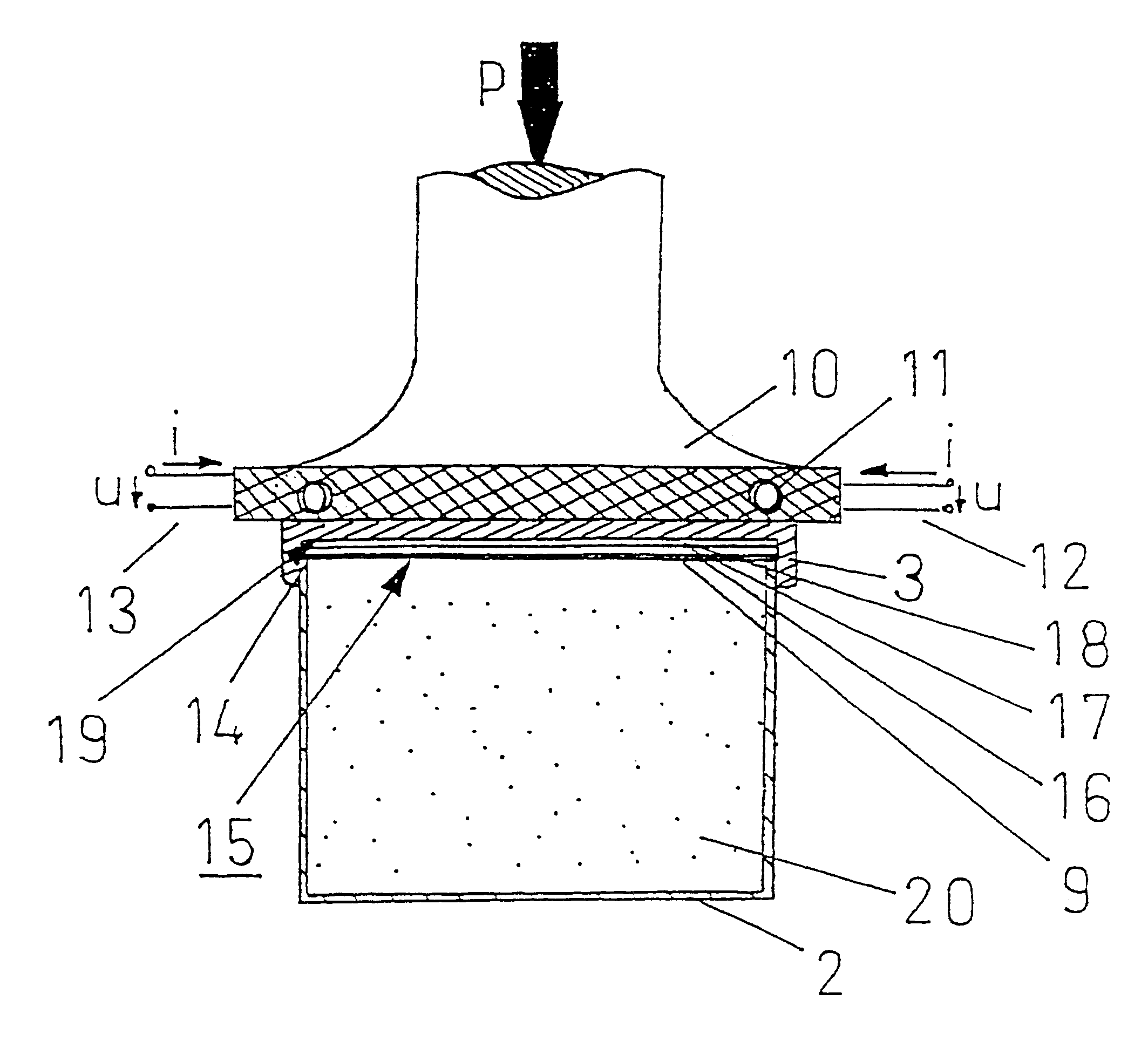
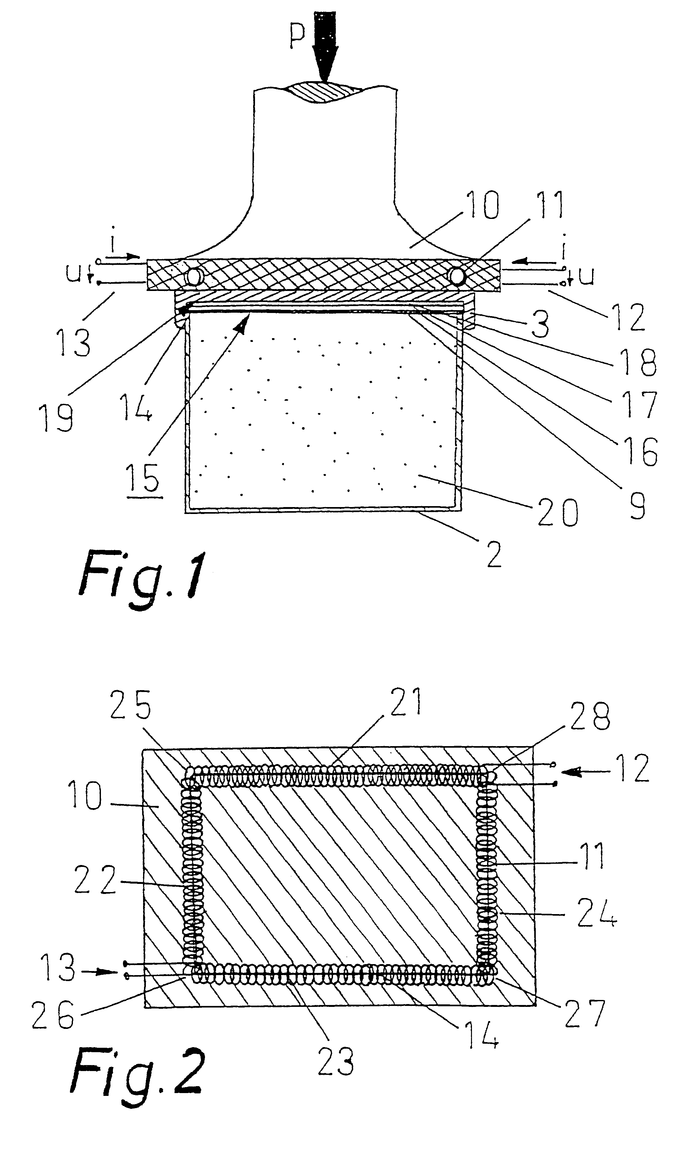
In FIG. 1 a sectional view through an induction loop 11 according to the invention in a plunger 10 is shown. The plunger 10 is provided to hold an induction loop 11. The induction loop 11 is formed as a dual coil. In this way the disadvantage which arises with induction loops with only one coil in the region of the inlet and outlet for the current, in other words a slight non-homogeneity, is avoided. The inlets and outlets for the current are indicated for the dual coils of the induction loop 11 by the reference numerals 12 and 13.

On the upper edge of the container, at the sealing edge 14 of the container 2, a sealing washer 15 is arranged. The sealing washer 15 has three layers. Adjoining the upper edge of the container 2 a sealing layer 9 is provided, and over this a metal foil 16, for example an aluminum foil. The sealing layer 9 preferably covers the whole metal foil 16. During the sealing process it melts in the region of the sealing edge 14, and therefore consists of a sealing...

second embodiment

FIG. 3 shows a plan view of an induction loop according to the invention with container arranged underneath. The container 2 has an octagonal shape, as has its sealing edge 14. This is indicated in FIG. 3 by a line.

The induction loop 38 is arranged above the sealing edge 14 on the lid of the container 2. In contrast to the embodiment according to FIG. 1 or 2, in the embodiment according to FIG. 3 no plunger is provided. The induction loop 38 is provided without a plunger. It is arranged above the container closed with a lid and seals the sealing edge 14 with a sealing washer, without itself exerting any pressure on the lid. The required pressure is already provided by the lid screwed on to the container orifice. A further production of pressure is therefore no longer necessary for the sealing process. Alternatively the induction process can take place completely without pressure. The sealing washer is herein not pressed on to the edge of the seal by the lid.

Nevertheless, its sealing...


PUM

PropertyMeasurementUnit
Timeaaaaaaaaaa
Pressureaaaaaaaaaa
Sizeaaaaaaaaaa

Abstract

A sealing device for sealing non-circular, in particular polygonal, for example tetragonal, hexagonal, octagonal or elliptical, container openings comprises one or a plurality of induction loops (11, 38, 41) for sealing purposes. Containers (2) comprise joined-on closure devices (3) with sealing discs (15) joined onto a sealing edge (14) of the container opening. The induction loops (11, 38, 41) are adapted to the shape of the sealing edge (14) and the spacing between the induction loop (11, 38, 41) and sealing edge (14) is constantly adjustable and selectable.

Description

The invention relates to a sealing device for sealing non-circular, in particular polygonal, such as tetragonal, hexagonal, octagonal or elliptical, container orifices, wherein one or more induction loops are provided for sealing and the induction loops are adapted to the shape of the edge of the seal, and a process for sealing such container orifices, as well as a sealing washer used therein.BACKGROUND OF RELATED ARTFor economical stacking of receptacles they are preferably produced as non-circular tins, in particular tetragonal tins, for example for cocoa powder. Hereby more rectangular tins can be accommodated on the same floor space than with the provision of round tins. The latter are, however, preferred in production.It is in fact found that the sealing of angular tins proves to be more difficult than the sealing of round tins. Therefore angular containers are frequently provided with round upper orifices. Tetragonal glass containers, the upper orifice edge of which can be glu...

Claims


Application Information

Patent Timeline
IPC IPC(8): B29C65/02B65B7/28B65B51/22H05B6/44H05B6/36B29C65/04
CPCB29C65/3656B29C66/542B29C65/368B29C66/72321B29C66/80B65B7/28B65B51/227H05B6/44B29C65/3668B29C65/3644B29C66/242B29C66/24225B29C66/2424B29C66/24243B29C66/24244B29C66/24249B29C65/00B29C66/8322B29C66/934B29C66/71B29C66/1222B29C66/1224B29K2067/00B29K2027/06B29K2023/12B29K2023/065
Inventor WIENING, HEINZ-RUDOLFTROMBACH, HORST
Owner ALFELDER KUNSTWERKE HERM MEYER
Why Eureka
Try Eureka