
Method and device for detecting jacquard shed anomalies

Inactive Publication Date: 2002-03-19
STAUBLI FAVERGES SA
View PDF7 Cites 15 Cited by
  • Summary
  • Abstract
  • Description
  • Claims
  • Application Information

AI Technical Summary

Benefits of technology

The method of the invention takes advantage of the fact that it is possible to determine the efforts exerted by an electrical actuator without resorting to ancillary mechanical devices, while the operations of memorization, comparison and logic processing may be carried out in an electronic controller used, furthermore, for controlling the actuators. The method of the invention dispenses with the operation of threading of the warp stop motion drop wires, this allowing an appreciable saving of time and consequently reducing the operating costs of the loom. In addition, the method allows a rapid and precise identification of the position of a warp yarn at the level of which the shed does not conform to the desired weave, whether it be due to a rupture of this yarn, to a dysfunction of the elastic return means or to a defect in the kinematic link between the actuator and the heddle, as the actuator for which an anomaly signal is generated is immediately located.
Finally, the invention relates to a Jacquard type weaving loom equipped with a device as described hereinbefore. Such a loom is more economical than the looms equipped with conventional warp stop motion devices, while it is easier to use for an operator and it does not require tedious threading operations. In addition, such a loom may allow automatized repairs when an anomaly is observed, as the device and the method of the invention allow a precise identification of the cause of an anomaly and its physical location on the loom.

Problems solved by technology

However, such a warp stop motion device presents considerable limitations.
This operation may be long and requires qualified manpower.
In addition, the positioning of the metallic drop wires on the different warp yams, sometimes called "threading", is a long and expensive operation.
Moreover, the known warp stop motion devices are sensitive to pollution due to the flock which is most often produced during the weaving operations.

Method used


Image

  • Method and device for detecting jacquard shed anomalies
  • Method and device for detecting jacquard shed anomalies
  • Method and device for detecting jacquard shed anomalies

Examples


Embodiment Construction

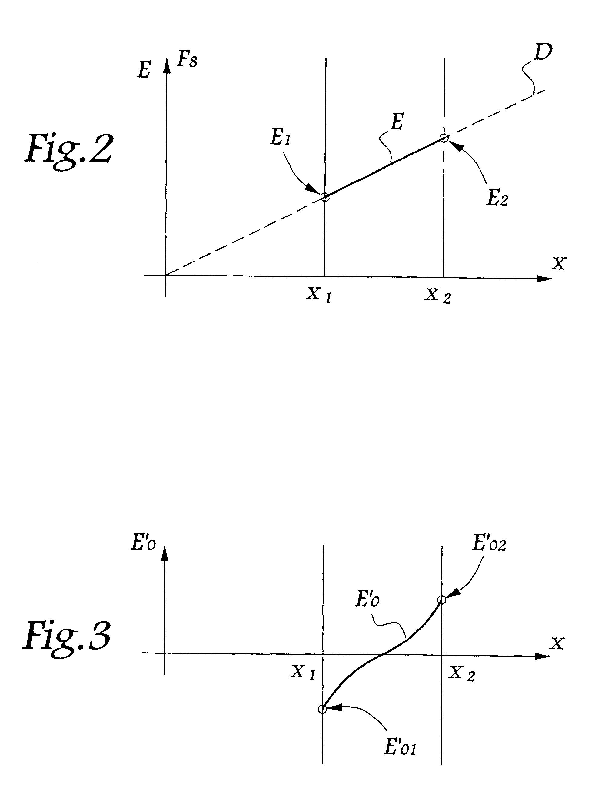
Referring now to the drawings, the efforts represented in FIGS. 2 to 5 are static efforts. In practice, real dynamic efforts incorporate oscillatory components due to the vibrations, as well as forces of inertia and of friction, these components and these forces not being shown in order to render the drawings clearer.

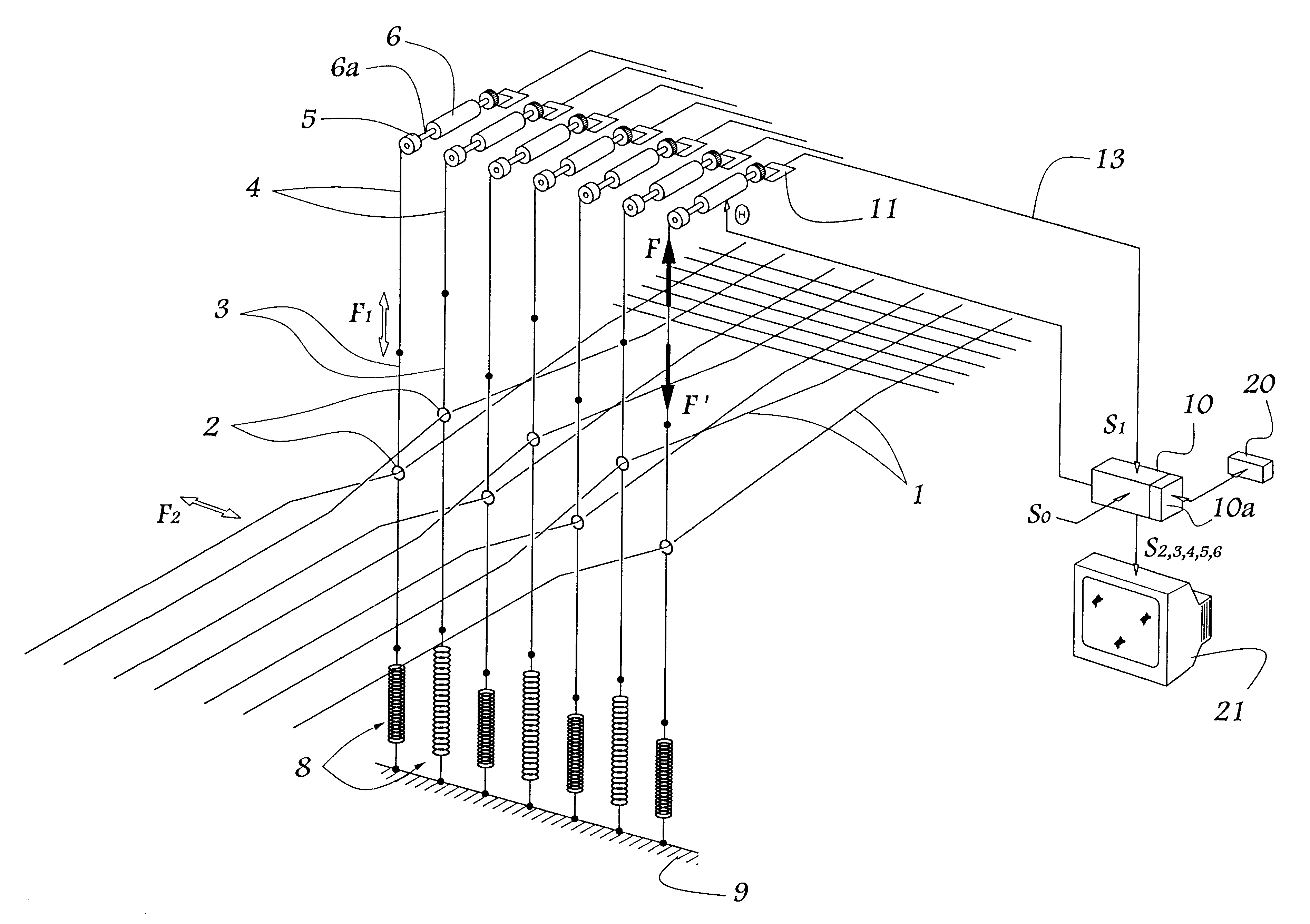
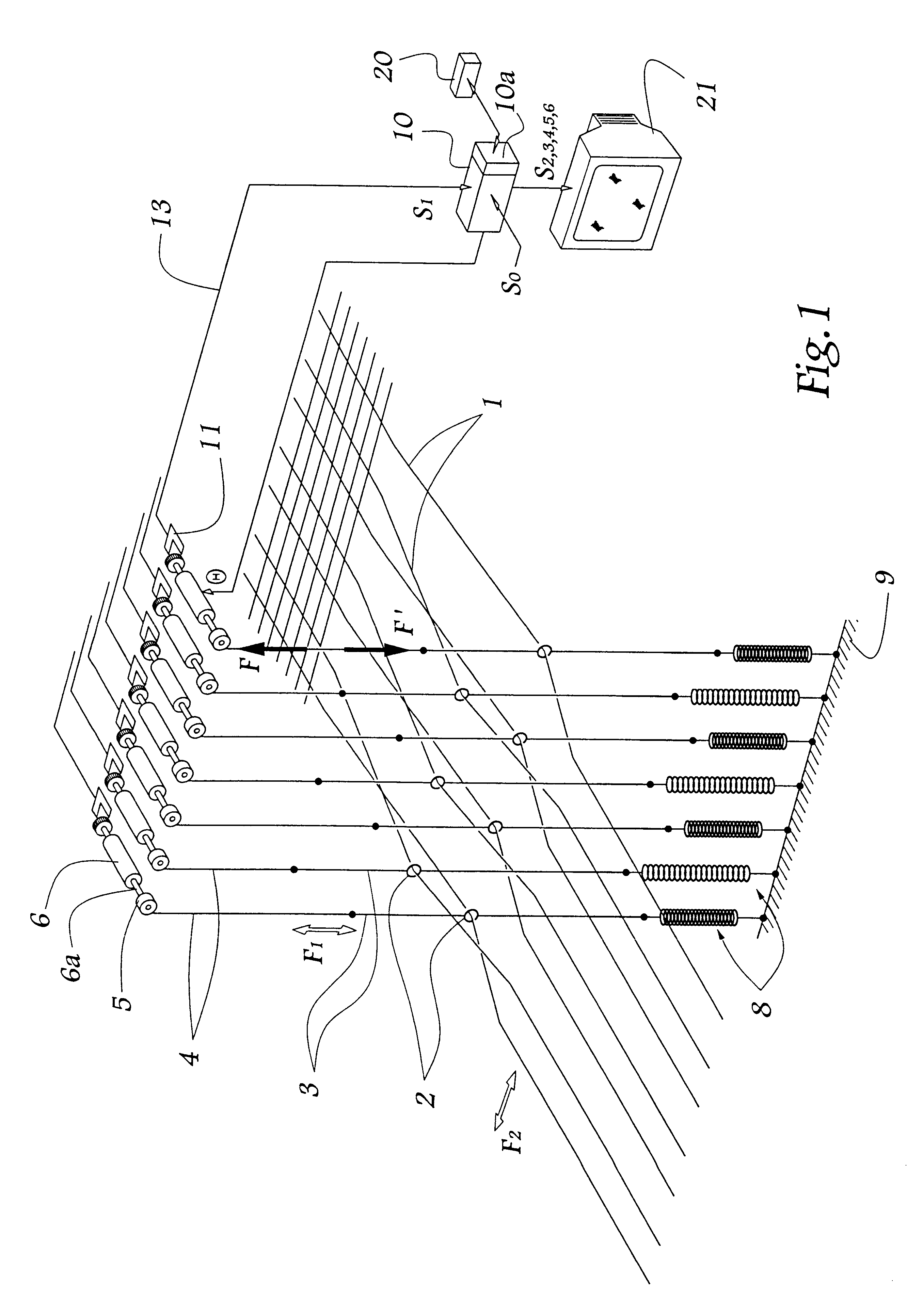
The weaving loom shown schematically in FIG. 1 comprises warp yarns 1 each traversing an eyelet 2 of a heddle 3 animated by a vertical movement of oscillation, represented by arrow F.sub.1 substantially perpendicular to the direction of the movements of the weft yarns represented by arrow F.sub.2. Each heddle 3 is connected by a harness cord 4 to a pulley 5 driven in rotation by an electric servomotor 6. In its lower part, each heddle 3 is connected to a spring 8 secured to the frame 9 of the loom.

As represented for the motor 6 furthest to the right in FIG. 1, each motor is controlled in position by a monitoring unit 10 which receives a position setting signal S.sub.0.

A...


PUM


Abstract

In a weaving loom of the Jacquard type comprising electrical actuators for displacing heddles controlling the position of the warp yarns, the following steps are carried out:a so-called "normal effort" is determined, exerted by at least one actuator on at least one harness cord in order to displace, between two positions of its normal stroke, at least one heddle connected to a normally taut warp yam;from this normal effort, at least one threshold value representative of a limit of a range of values of normal weaving effort is determined;while the loom is in operation, a so-called "operational effort" exerted by this actuator on the harness cord is determined;at least one value representative of this operational effort is compared with the threshold value, anda first, so-called "anomaly signal" is generated when the value representative of the operational effort is outside the afore-mentioned range.The device comprises a logic unit incorporating a comparator and associated with a memory and a display means.

Description

1. Field of the InventionThe present invention relates to a method and to a device for detecting an anomaly in the formation of the shed in a Jacquard-type weaving loom. The invention also concerns a weaving loom equipped with such a device.2. Brief Description of the Related ArtFR-A-2 772 796 for example discloses using an electrical actuator for controlling the displacement of the harness cords of a Jacquard loom harness.Furthermore, it is known to equip a Jacquard-type weaving loom with a so-called "warp stop motion" device which comprises metallic drop wires supported by each of the warp yarns of the loom and conducting bars extending over the width of the loom. In the event of rupture of a warp yam, the drop wire that it supports comes, under the effect of its own weight, into contact with conducting bars, which creates an electrical contact between these conducting bars which are made alive. Such contact can be detected by an electrical monitoring system, which makes it possib...

Claims


Application Information

Patent Timeline
IPC IPC(8): D03D51/46D03D51/18D03D51/28D03C3/00D03D51/20
CPCD03C3/205D03D51/46D03D51/28
Inventor BRAUN, DOMINIQUE
Owner STAUBLI FAVERGES SA
Learn More