Electromechanical brake for motor vehicles

a technology of electronic brake and motor vehicle, which is applied in the direction of mechanical equipment, braking systems, transportation and packaging, etc., can solve the problems of not always ensuring the automatic release of the brake lining, the lack of friction of the planetary roller screw drive, and the inability to automatically restore the spindle rod

Inactive Publication Date: 2002-01-08
ROBERT BOSCH GMBH
View PDF12 Cites 9 Cited by
  • Summary
  • Abstract
  • Description
  • Claims
  • Application Information

AI Technical Summary

Problems solved by technology

The desired lack of friction of the planetary roller screw drive is therefore not achieved so that an automatic release of the brake lining is not always assured in the event of a malfunction.
Due to the relatively large area of contact between the spindle rod and the slide bearing, there is no automatic restoring of the spindle rod in the event of a drive motor failure.

Method used


Image

  • Electromechanical brake for motor vehicles
  • Electromechanical brake for motor vehicles
  • Electromechanical brake for motor vehicles

Examples


Embodiment Construction

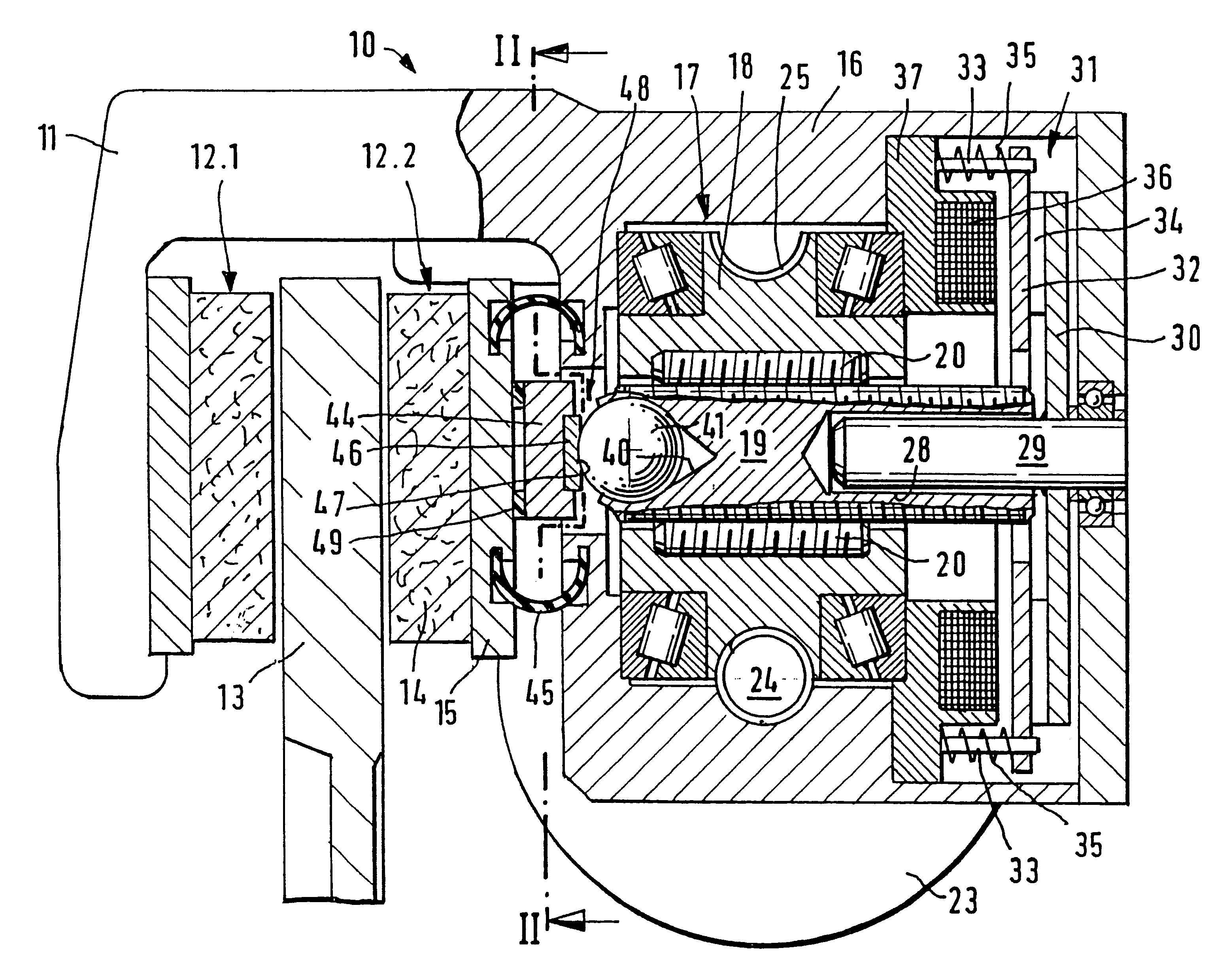
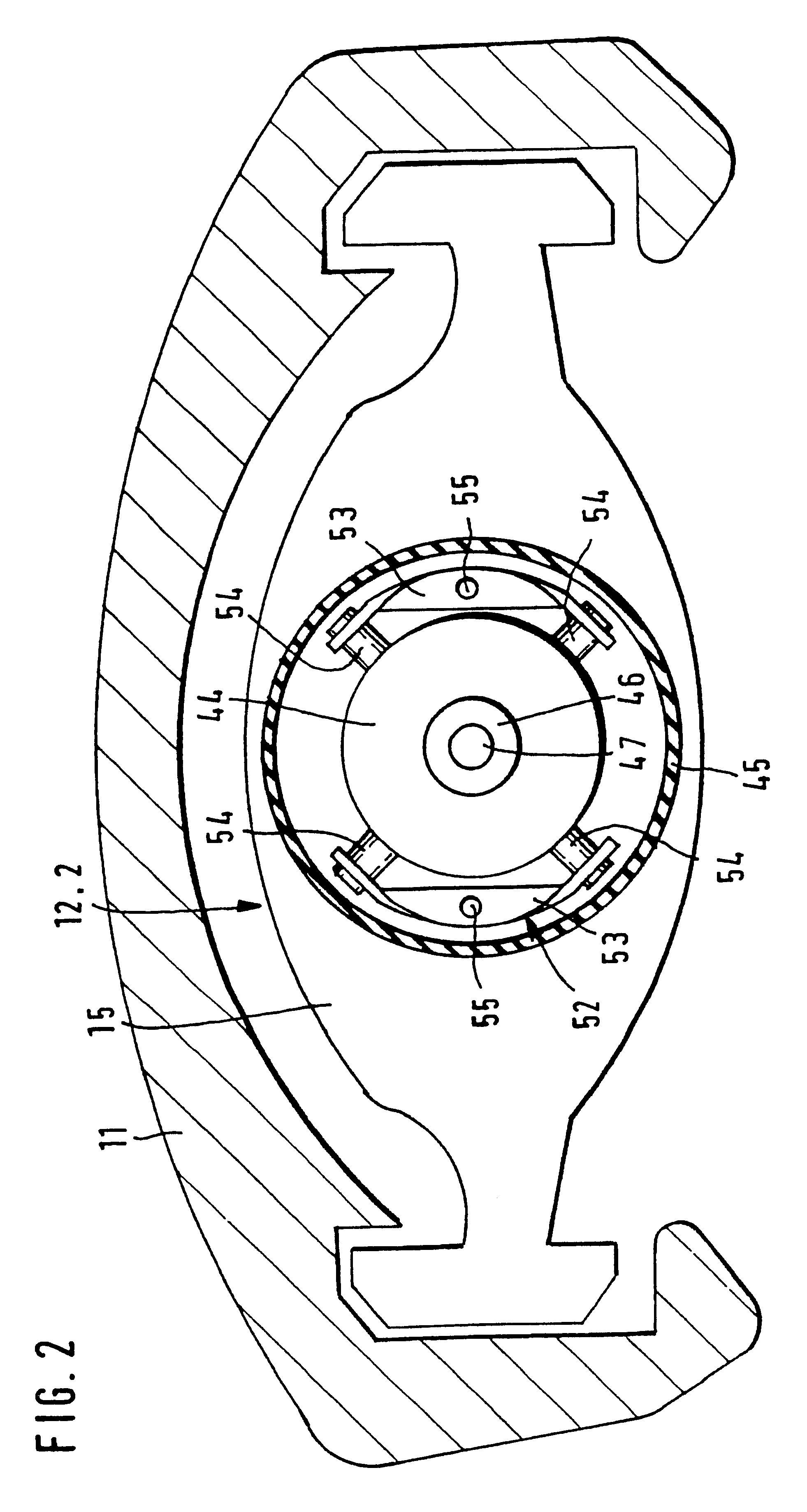
An electromechanical brake 10 shown in FIG. 1 is embodied as a disc brake. It has a caliper 11, which accommodates a pair of friction brake linings 12.1 and 12.2 on both sides of a brake disc 13, which acts as a rotating friction element. The brake lining 12.1 is fastened to the caliper 11, the brake lining 12.2 is supported so that the brake lining can slide in the caliper. The brake linings 12.1 and 12.2 are comprised of a brake wearing layer 14 and a steel base plate 15 connected to the brake wearing layer. In order to press the brake linings 12.1 and 12.2 against the brake disc 13, a selflocking-free screw link actuator 17 in the form of a planetary roller screw drive is disposed in a housing 16 that is adjoined to the caliper 11. This planetary roller screw drive has a spindle nut 18 that is supported so that the spindle nut can rotate in the housing 16, a threaded spindle 19 that reaches through this spindle nut, and a number of threaded rollers 20 disposed between the spindle...


PUM


Abstract

An electromechanical brake for motor vehicles having a selflocking-free spindle that is electromotively moved bidirectionally in a longitudinal direction in order to press at least one brake lining against a rotating friction element in an advancing stroke and and in order to release the brake lining in a restoring stroke. The brake also has a plate-shaped coupling member between the spindle and the brake lining. The coupling member engages directly with the spindle and is supported against the brake lining so that the brake lining slides lateral to the longitudinal axis of the spindle. This largely prevents lateral forces, which interfere with the lack of friction of the spindle and can occur when the brake lining is against the friction element. The electromechanical brake is used in passenger motor vehicles.

Description

PRIOR ARTThe invention is based on an electromechanical brake for motor vehicles.In brakes of this kind, an automatic release of the friction lining must be assured in the event of a failure of the electric drive motor during a braking maneuver. In a disc brake of this type, which is known from WO96 / 03301, a push rod is therefore disposed between the spindle and the plate-shaped coupling member fastened to the brake lining in order to minimize friction-induced efficiency losses inside a selflocking-free planetary roller screw drive that contains the spindle. Since the brake lining in the caliper has a play that is necessary for the proper functioning of the disc brake, when the brake lining presses against the brake disc, a displacement of the coupling element attached to the brake lining takes place, both in the disc circumference direction and lateral to this, with the result that the push rod transmits lateral forces onto the spindle. The desired lack of friction of the planetary...

Claims


Application Information

Patent Timeline
Patent Type & Authority Patents(United States)
IPC IPC(8): B60T13/74B60T13/00F16D65/14F16D65/16F16D65/18F16D65/28
CPCB60T13/741F16D65/18F16D2121/24F16D2127/06F16D2125/52F16D2125/587F16D2125/40
Inventor SCHAFFER, WOLFRAM
Owner ROBERT BOSCH GMBH
Why Eureka
Try Eureka