
Device for packaging and applying a substance, the device having a wiper member with a slot

Inactive Publication Date: 2001-12-11
LOREAL SA
View PDF10 Cites 120 Cited by
  • Summary
  • Abstract
  • Description
  • Claims
  • Application Information

AI Technical Summary

Benefits of technology

By means of the invention, it is possible to wipe the applicator element in particularly satisfactory manner, particularly when the element is substantially flat, such as a brush, a comb, or a body covered in flock, with the plane of the element extending substantially parallel to the slot of the wiper member.
The wiper member is preferably organized in such a manner that the slot opens more easily while the applicator is being inserted into the receptacle than while it is being withdrawn therefrom.
This makes it possible to reduce the risk of the applicator element being damaged when the applicator is reinserted, while nevertheless maintaining satisfactory wiping of the applicator element while the applicator is being withdrawn.
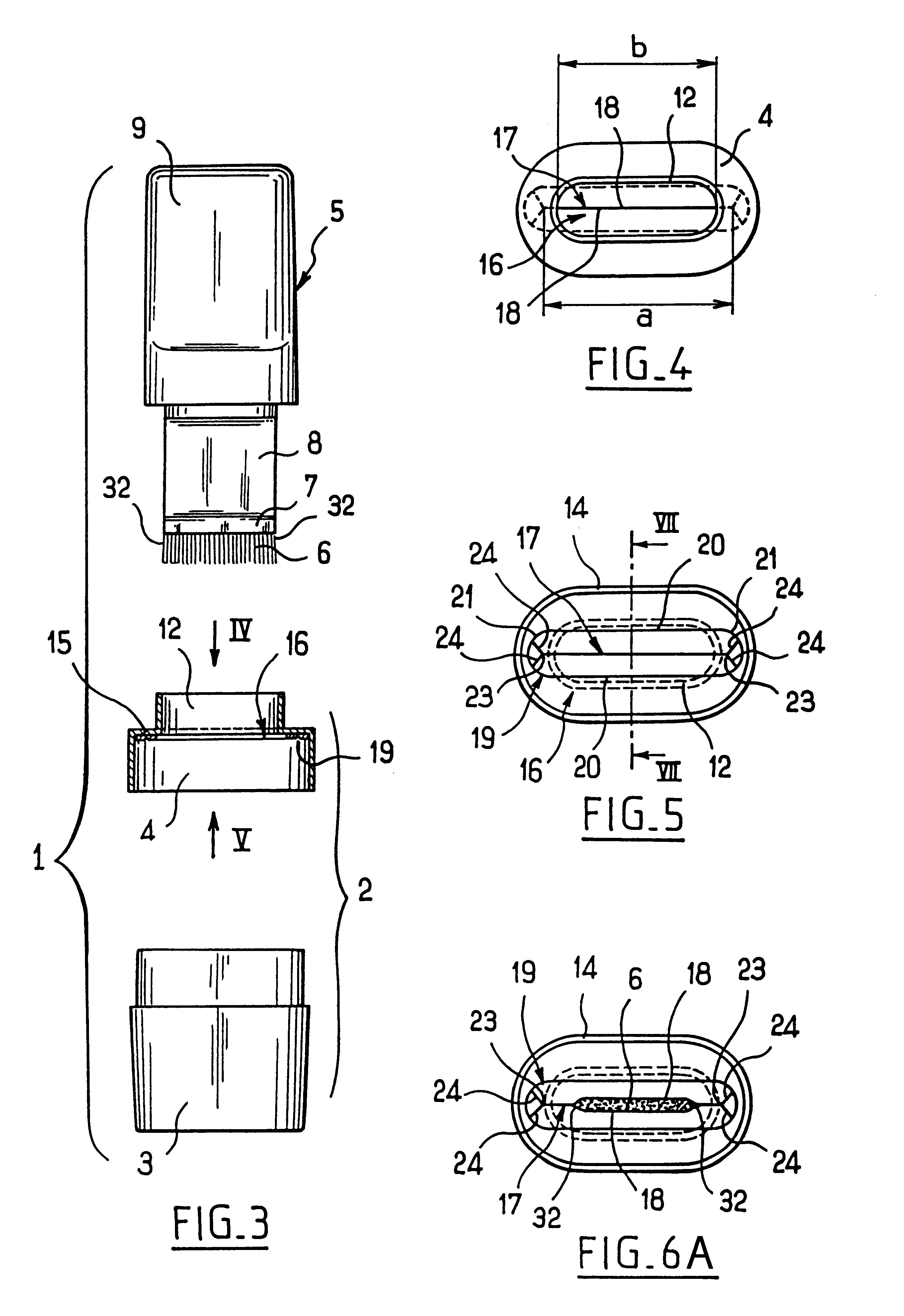
In a particular embodiment, the slot is extended at its axial ends by cutouts for the purpose of conferring greater mobility to its longitudinal edges. These cutouts advantageously form an angle with the longitudinal edges of the slot.
Preferably, the membrane is fixed on a wall of the receptacle in such a manner that the longitudinal edges of the slot can pivot towards the inside of the receptacle, going away from said wall, while the applicator is being reinserted, and come to bear against said wall while the applicator is being withdrawn. In this way, the edges of the slot bear more strongly against the applicator element while the applicator is being withdrawn than while it is being reinserted into the receptacle, which is advantageous, as explained above.
The membrane can be fixed, for example, on an insertion cone of the receptacle for the purpose of facilitating insertion of the applicator into the receptacle.

Problems solved by technology

In particular because of the presence of the above-mentioned orifice, the end of the applicator element cannot be wiped in satisfactory manner.
Nothing in such a device prevents the comb from reaching the ends of the slot of the wiper member while the comb is being withdrawn.
Such a device does not enable the end of the applicator element to be wiped in completely satisfactory manner over its entire length.

Method used


Image

  • Device for packaging and applying a substance, the device having a wiper member with a slot
  • Device for packaging and applying a substance, the device having a wiper member with a slot
  • Device for packaging and applying a substance, the device having a wiper member with a slot

Examples


Embodiment Construction

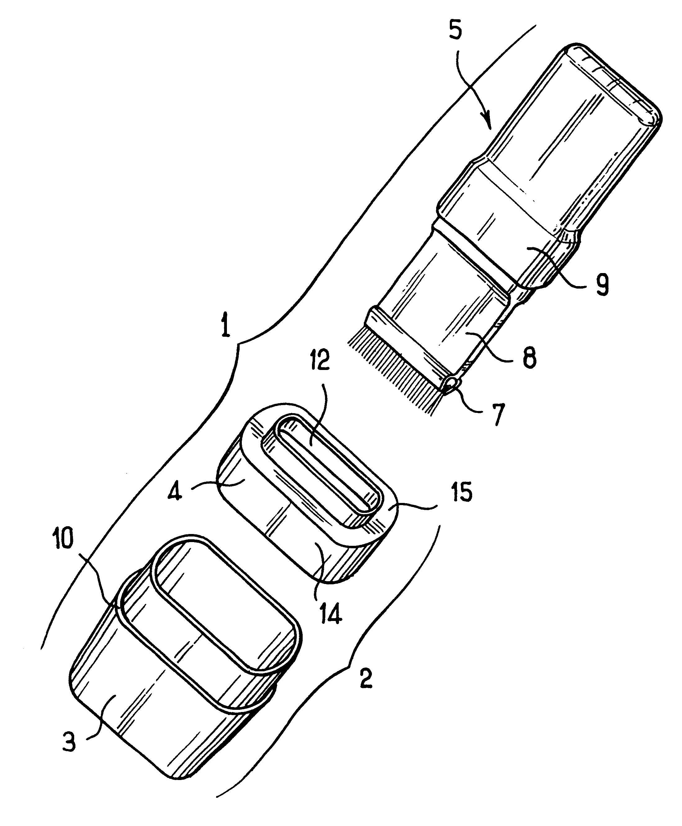
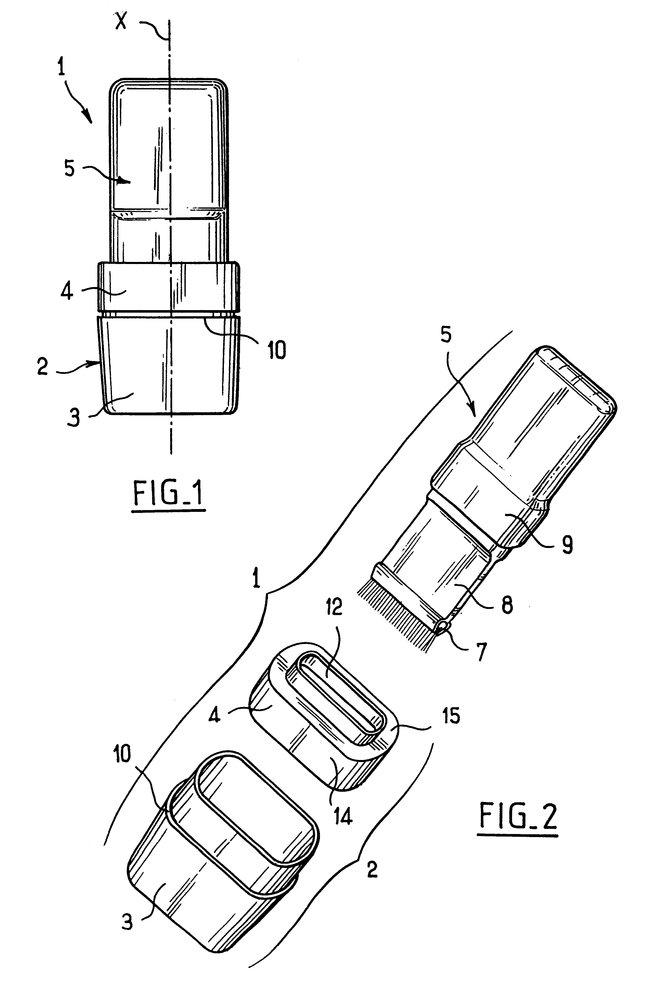
The packaging and applicator device 1 shown in FIGS. 1 to 3 comprises a receptacle 2 of axis X, having a body 3 provided at its top portion with a cover 4, and with an applicator 5.

The applicator 5 comprises an applicator element 6, for example including a brush, a foam, a flock-covered body, a comb, hairs or teeth, situated at the bottom end 7 of a thin flat rod 8 which is provided at its top end with a handle 9 that also constitutes a closure cap for the receptacle 2.

The applicator may have a sealing element for closing the receptacle in leakproof manner.

In the example described, the rod 8 is 1 mm thick and 23 mm wide.

The receptacle 2 is designed to contain any substance in liquid, semisolid, or powder form, in particular a cosmetic such as mascara.

In the example described, the body 3 and the cover 4 are made by molding a plastics material.

The body 3 has an outer shoulder 10 and the cover 4 has a skirt 14 shaped to engage on the top portion of the body 3, as shown in FIG. 1.

In the...


PUM


Abstract

A device for packaging and applying a substance, in particular a cosmetic, the device comprising a receptacle for containing said substance, an applicator having an applicator element of elongate cross-section, and a wiper member for wiping the applicator element when the applicator is extracted from the receptacle, wherein the wiper member has a slot whose edges are substantially touching at rest in the absence of the applicator, and wherein the device further comprises a guide member for guiding the applicator while it is being extracted from the receptacle and for keeping the applicator element away from the axial ends of said slot while it passes through the wiper member as the applicator is being withdrawn.

Description

The present invention relates to a device for packaging and applying a substance, in particular a cosmetic.The invention relates more particularly to a packaging and applicator device comprising a receptacle for containing the substance and an applicator comprising an applicator element, the receptacle being provided with a wiper member for wiping the applicator element when the applicator is extracted from the receptacle at the time of use.Numerous packaging and applicator devices of that type are known.Application NO 91 / 01097 discloses a device comprising a receptacle and an applicator of circular cross-section that is constituted by a brush. Such a device has a wiper member constituted by a split membrane which is provided with a central orifice whose section corresponds substantially to that of the applicator. In particular because of the presence of the above-mentioned orifice, the end of the applicator element cannot be wiped in satisfactory manner.British patent 452 640 discl...

Claims


Application Information

Patent Timeline
IPC IPC(8): A45D40/26A45D34/04
CPCA45D40/267
Inventor GUERET, JEAN-LOUIS
Owner LOREAL SA
Learn More