
Skeleton model shape transformation method, image synthesizing apparatus, and information storage medium

a technology of image synthesizer and skeleton model, which is applied in the field of transforming the shape of skeleton model, an image synthesizer and information storage medium, can solve the problems of difficult to obtain the inverse function, troublesome work, and difficult to handle a multiple-branch operation

Inactive Publication Date: 2001-11-20
BANDAI NAMCO ENTERTAINMENT INC
View PDF2 Cites 41 Cited by
  • Summary
  • Abstract
  • Description
  • Claims
  • Application Information

AI Technical Summary

Problems solved by technology

However, since the function f is non-linear, it is not easy to obtain this inverse function.
1. It is Difficult to Handle a Multiple-branching Structure
The user must therefore work while constantly being aware of which node acts as the root and which node acts as effector, which makes the work troublesome.
2. It is Difficult to Handle Complicated Restrictive Conditions
If restrictive conditions are set for a plurality of nodes, for example, it is necessary to divide the skeleton into suitable directly linked structures before handling it, so that the processing becomes complicated.
However, the basic variables used in the prior-art technique are the arc-to-arc angles, so it is difficult to use the above equations and thus restrictive conditions are difficult to handle.
3. It is Difficult to Move a Plurality of Nodes in Different Directions Simultaneously
In other words, if an attempt is made to move nodes 38 and 39 in different directions simultaneously, for example, with the prior-art technique, the processing is extremely complicated.
If a long time is requires for the second variable to converge on the given convergent value, or escape from that convergent state, the speed of response of the skeleton model with respect to the user's input will deteriorate.

Method used


Image

  • Skeleton model shape transformation method, image synthesizing apparatus, and information storage medium
  • Skeleton model shape transformation method, image synthesizing apparatus, and information storage medium
  • Skeleton model shape transformation method, image synthesizing apparatus, and information storage medium

Examples


embodiment

1 Concept of Embodiment

Basic Principles

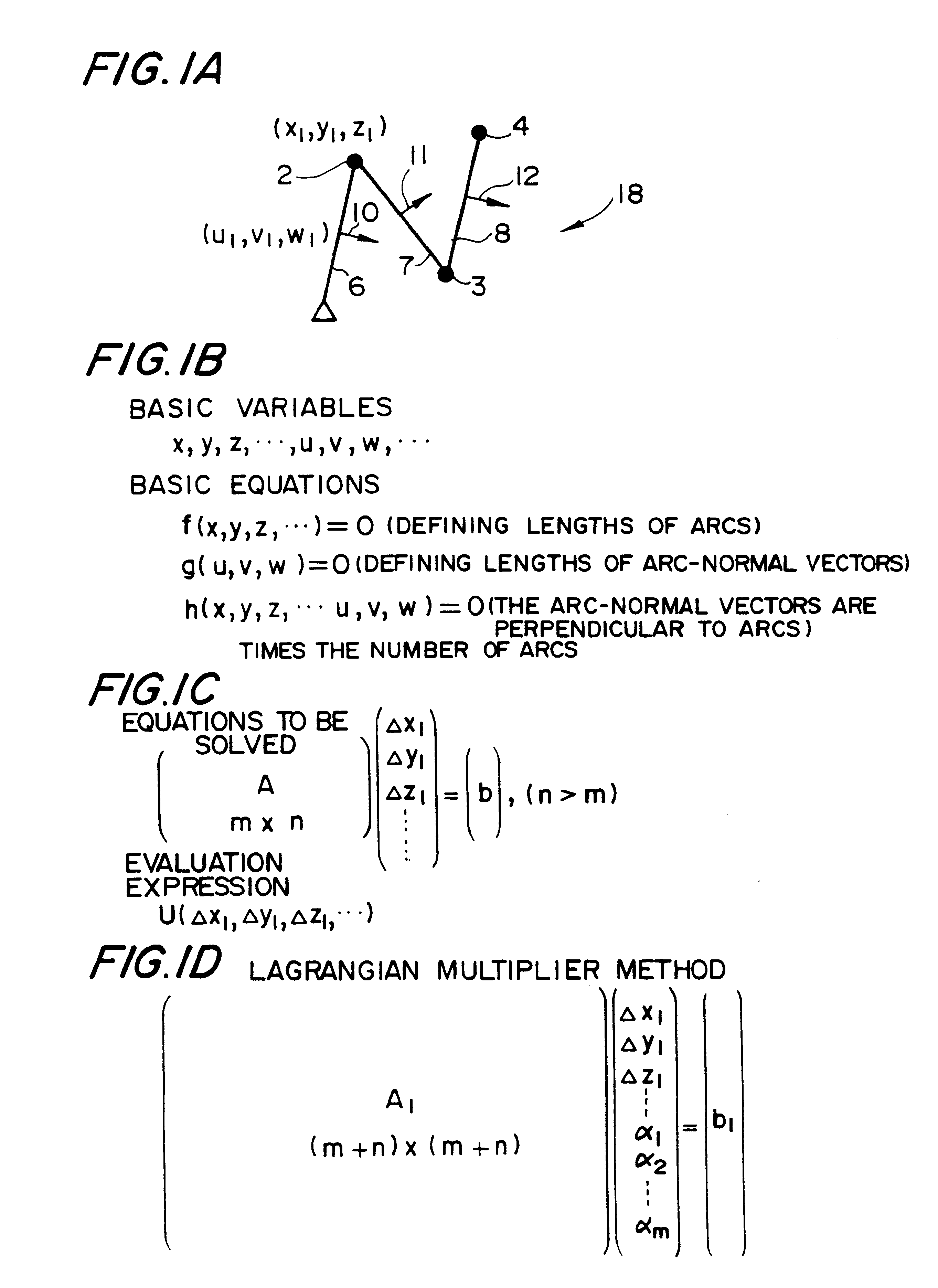
In this embodiment, the (x, y, z) coordinates of nodes 2, 3, and 4 and the (u, v, w) components of arc-normal vectors 10, 11, and 12 (which are perpendicular to arcs 6, 7, and 8, respectively) are used as basic variables representing a skeleton model 18, as shown in FIG. 1A. Taking as an example the prior-art model of FIGS. 22A, 22B, and 22C, which uses arc-to-arc angle as basic variables, it is necessary to set parent-child relationships. With that prior-art technique, nodes and arcs cannot be handled uniformly, but this embodiment, which uses node coordinates and arc-normal vectors as basic variables, makes it possible to handle all nodes and arcs in a uniform manner. Note that other variables could equally well be used instead of arc-normal vectors, for example.

These basic variables are then used as unknowns in basic equations, as shown in FIG. 1B, which provide an equation defining the length of an arc as a given value, an equation definin...


PUM


Abstract

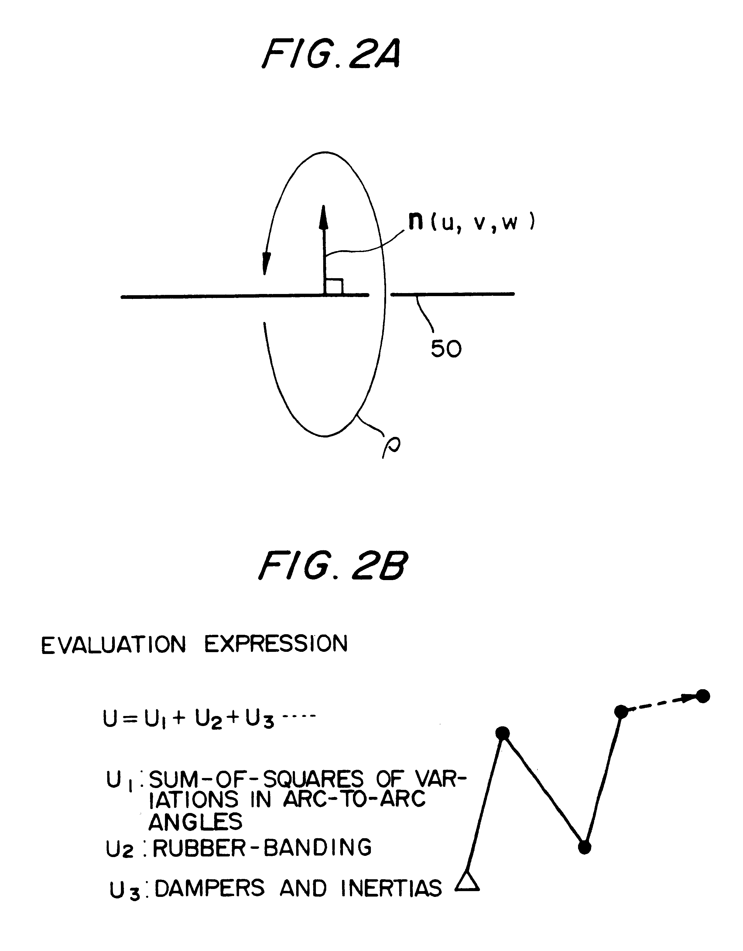
The objective of this invention is to provide a method of transforming the shape of a skeleton model, wherein this method can easily handle a skeleton model of a multiple-branching structure and enables the easy setting of complicated restrictive conditions. Node coordinates and arc-normal vectors are used as basic variables. Basic equations, which comprise an equation defining the length of an arc and which use basic variables as unknowns, and an evaluation expression for uniquely specifying a solution that satisfies these basic equations are modified, based on data such as mouse input. A solution for the basic variables that satisfies the basic equations and minimizes the value of the evaluation expression is obtained, and the shape of the skeleton model is transformed accordingly. The evaluation expression is used to set minimization of the sum-of-squares of arc-to-arc angles, rubber-banding, dampers, and inertia. The basic equations and the evaluation expression are updated in synchronization with the end of a loop. A spring restriction can be set, and the use of a restrictive condition in the next loop of the calculations can be determined from whether or not the restrictive condition was used in the previous loop, and whether or not an object has passed a boundary.

Description

1. Field of the InventionThis invention relates to a method of transforming the shape of a skeleton model, an image synthesizing apparatus, and an information storage medium.2. Description of Related ArtA technique called inverse kinematics is known in the art. With this technique, a skeleton model 20 such as that shown in FIG. 22A is created beforehand within a computer. The user then uses an input device such as a mouse to transform that skeleton model 20 while viewing the skeleton model 20 on a display device, such as a CRT, to create any motion or pose that the user desires. It should be noted that each of the joint or end points of the skeleton model 20 is called a "node" in the description that follows, and a linking "bone" that connects two nodes is called an arc.Several methods of using this inverse kinematics technique are known in the art, such as is described in "Modeling and Animation Techniques for a Computer Generated Actor" (by Fukui Kazuo, reference material for a se...

Claims


Application Information

Patent Timeline
IPC IPC(8): G06T17/00
CPCG06T17/00A63F2300/6607
Inventor YAMAGUCHI, KENTAROBABA, TETSUJIYOSHIDA, HIROSHI
Owner BANDAI NAMCO ENTERTAINMENT INC
Learn More