Sealing device and process for sealing a moving surface with the sealing device

a sealing device and sealing element technology, applied in engine sealing, paper-making machines, textiles and paper, etc., can solve the problems of increasing costs, affecting the sealing effect, and generating loud nois

Inactive Publication Date: 2001-10-16
VOITH PATENT GMBH
View PDF13 Cites 14 Cited by
  • Summary
  • Abstract
  • Description
  • Claims
  • Application Information

AI Technical Summary

Benefits of technology

Based on the arrangement of the present invention, a defined sealing gap can be set and maintained during operation such that the desired sealing action may be achieved without pressing the sealing element against the relevant moving surface, thus, reducing wear of the sealing element to a minimum. Upon start-up of the paper machine, the sealing element may be pressed against the moving surface. During subsequent normal operation, the pressing of the sealing element against the moving surface may then be relieved by the reset element so that the sealing element is substantially no longer subject to any wear. Thus, lubricants are no longer necessary and the spray tubes required in the prior art may be eliminated. Further, the noise level is clearly reduced.
At least one of the loading and reset elements may be acted on by an adjustable pressure. Further, it may be advantageous for the loading element and a reset element to be acted upon by the adjustable pressure independently of each other.
The adjacently positioned loading elements and / or the adjacently positioned reset elements may be acted upon differently such that the sealing element may assume a skewed position relative to the moving surface during operation. In this manner, a gap may be formed between the sealing element and the moving surface that widens in the travel direction, which ventilates openings provided in the moving surface in a ventilation zone that follows a sealed zone. Thus, noise occurring, e.g., in the region of a transition between a vacuum zone and overpressure zone can be further reduced.
With such a widening gap in the travel direction of the moving surface, choked ventilation of a vacuum zone may be provided, whereby the respective noise level is reduced to a minimum.
In accordance with another feature of the present invention, the at least one loading element includes at least two loading elements positioned adjacent to each other in a travel direction of the moving surface, and the at least one reset element includes at least two reset elements positioned adjacent each other in the travel direction, and process further includes pressurizing the at least two loading elements with different pressures, whereby a widening gap between the sealing element and the moving surface in the travel direction is formed.

Problems solved by technology

However, the friction appearing between the sealing element and relevant moving surface results in significant wear of the sealing element.
To limit this wear, lubricants are generally applied to the sealing element via spray tubes, which increases costs.
Because of the sudden ventilation of the jacket perforations following the sealing ledge adjoining a respective vacuum zone, loud noise is also generated.
However, the design of this device also includes the disadvantage that, due to the frictional fixing, a respectively desired positioning of the sealing ledge cannot be maintained with the necessary accuracy.
Instead, there is a danger that the positioning of the sealing ledge may change due to vibrations resulting in a gap of undefined width consequently developing between the sealing ledge and the vacuum roll jacket.
This gap formation could lead to relatively high air leakage between the pressure chambers.

Method used


Image

  • Sealing device and process for sealing a moving surface with the sealing device
  • Sealing device and process for sealing a moving surface with the sealing device

Examples


Embodiment Construction

The particulars shown herein are by way of example and for purposes of illustrative discussion of the embodiments of the present invention only and are presented in the cause of providing what is believed to be the most useful and readily understood description of the principles and conceptual aspects of the present invention. In this regard, no attempt is made to show structural details of the present invention in more detail than is necessary for the fundamental understanding of the present invention, the description taken with the drawings making apparent to those skilled in the art how the several forms of the present invention may be embodied in practice.

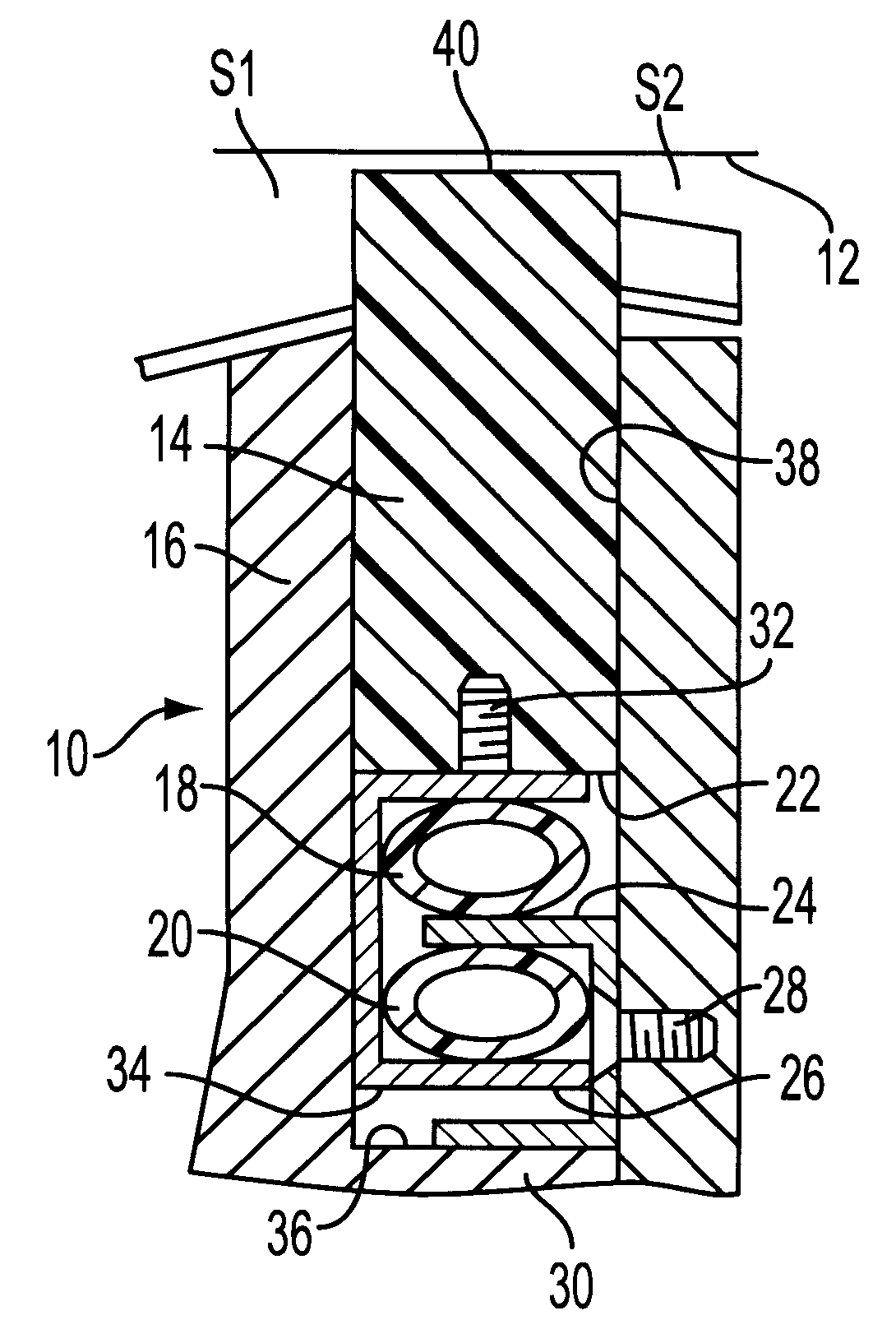
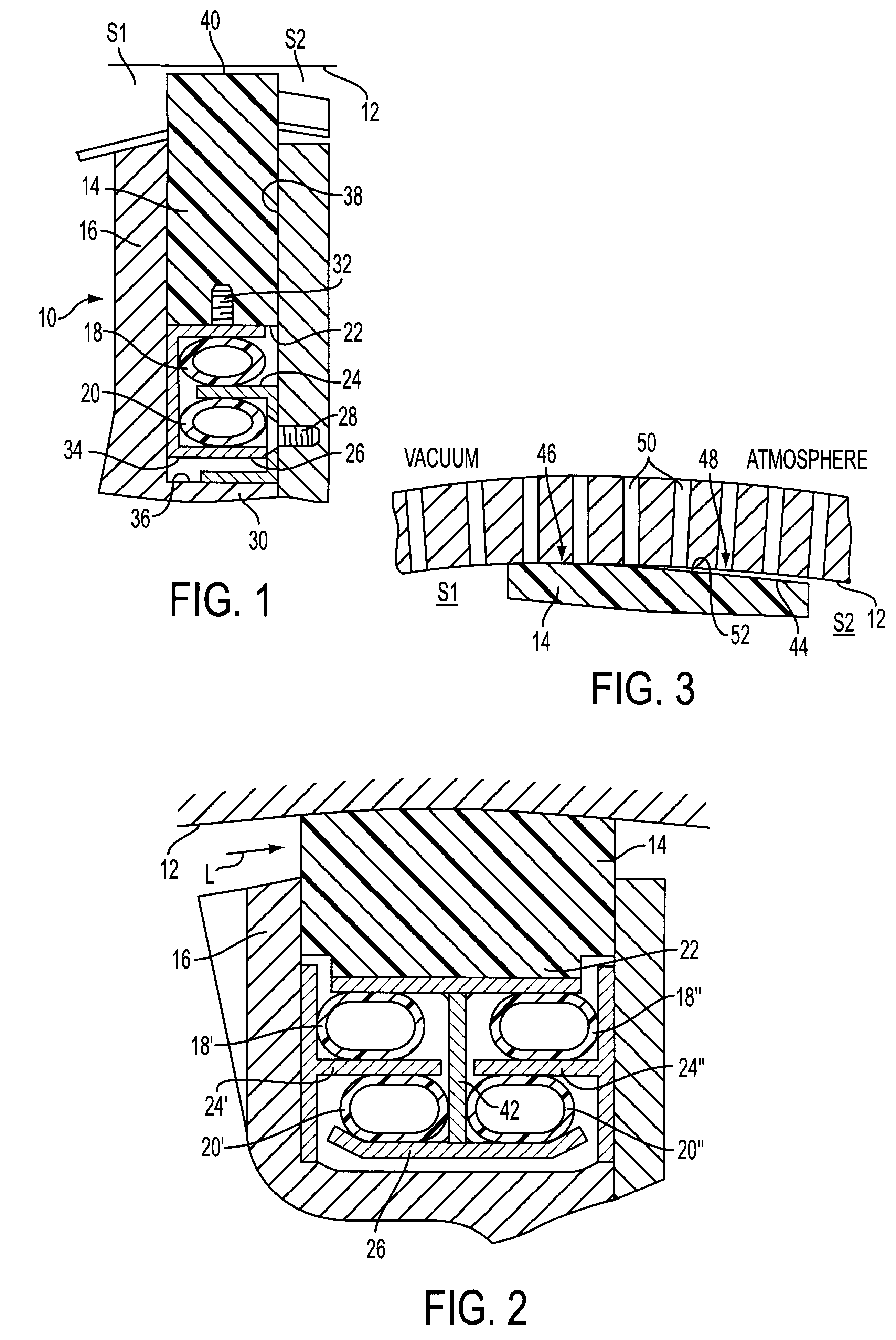
FIG. 1 schematically illustrates a first embodiment of the sealing device 10, which can be used, e.g., for laterally sealing at least one overpressure zone or vacuum zone adjacent to a moving surface 12. Moving surface 12 may be, e.g., an inside wall of a suction roll, and sealing device 10 may be positioned between a suction o...


PUM


Abstract

Sealing device for laterally sealing of at least one overpressure zone and vacuum zone in a paper machine and process for sealing a moving surface with the sealing device. The sealing device includes a moving surface adjacent to the at least one overpressure zone and vacuum zone, at least one sealing element positioned opposite the moving surface, a holder in which the sealing element is mounted for movement relative to the moving surface, at least one loading element arranged to load the sealing element in a direction toward the moving surface, and at least one reset element arranged to act against the at least one loading element and to move the sealing element away from the moving surface. A sealing gap formed during operation between the sealing element and the moving surface is set by at least one of the reset element and the loading element. The process includes pressurizing the at least one loading element to press the sealing element against the moving surface, and pressurizing the at least one reset element to press the sealing element against the at least one loading element and in a direction away from the moving surface, whereby a gap is formed between the sealing element and the moving surface.

Description

The present application claims priority under 35 U.S.C. .sctn.119 of German Patent Application No. 198 11 335.2, filed on Mar. 16, 1998, the disclosure of which is expressly incorporated by reference herein in its entirety.1. Field of the InventionThe present invention relates to a sealing device for laterally sealing at least one overpressure and vacuum zone adjacent to a moving surface in a paper machine and a process for sealing the moving surface with the sealing device. The sealing device includes at least one sealing element positioned adjacent to the moving surface, a holder in which the sealing element is mounted movably toward and away from the moving surface, and at least one loading element adapted to load the sealing element in the direction toward the moving surface.2. Discussion of Background InformationSealing devices such as those generally discussed above have been utilized in forming sections, press sections, and / or dry ends of a paper machine, e.g., in suction rol...

Claims


Application Information

Patent Timeline
IPC IPC(8): D21F1/48D21F3/10D21F3/02D21F7/00
CPCD21F1/483D21F3/10
Inventor PRINZING, HANS
Owner VOITH PATENT GMBH
Why Eureka
Try Eureka