
Tunable architecture for device adapter

a device adapter and adapter technology, applied in the direction of cad circuit design, instruments, software simulation/interpretation/emulation, etc., can solve the problems of not necessarily achieving optimal matching to a particular device, device interface to a bus not operating in isolation, and processors becoming unavailable for other tasks, etc., to achieve a high degree of configuration

Inactive Publication Date: 2001-09-18
TAIWAN SEMICON MFG CO LTD
View PDF30 Cites 24 Cited by
  • Summary
  • Abstract
  • Description
  • Claims
  • Application Information

AI Technical Summary

Benefits of technology

It is yet another object of the present invention to provide general purpose device adapter macro which can be customized, via user specified parameters, for a particular attaching device.
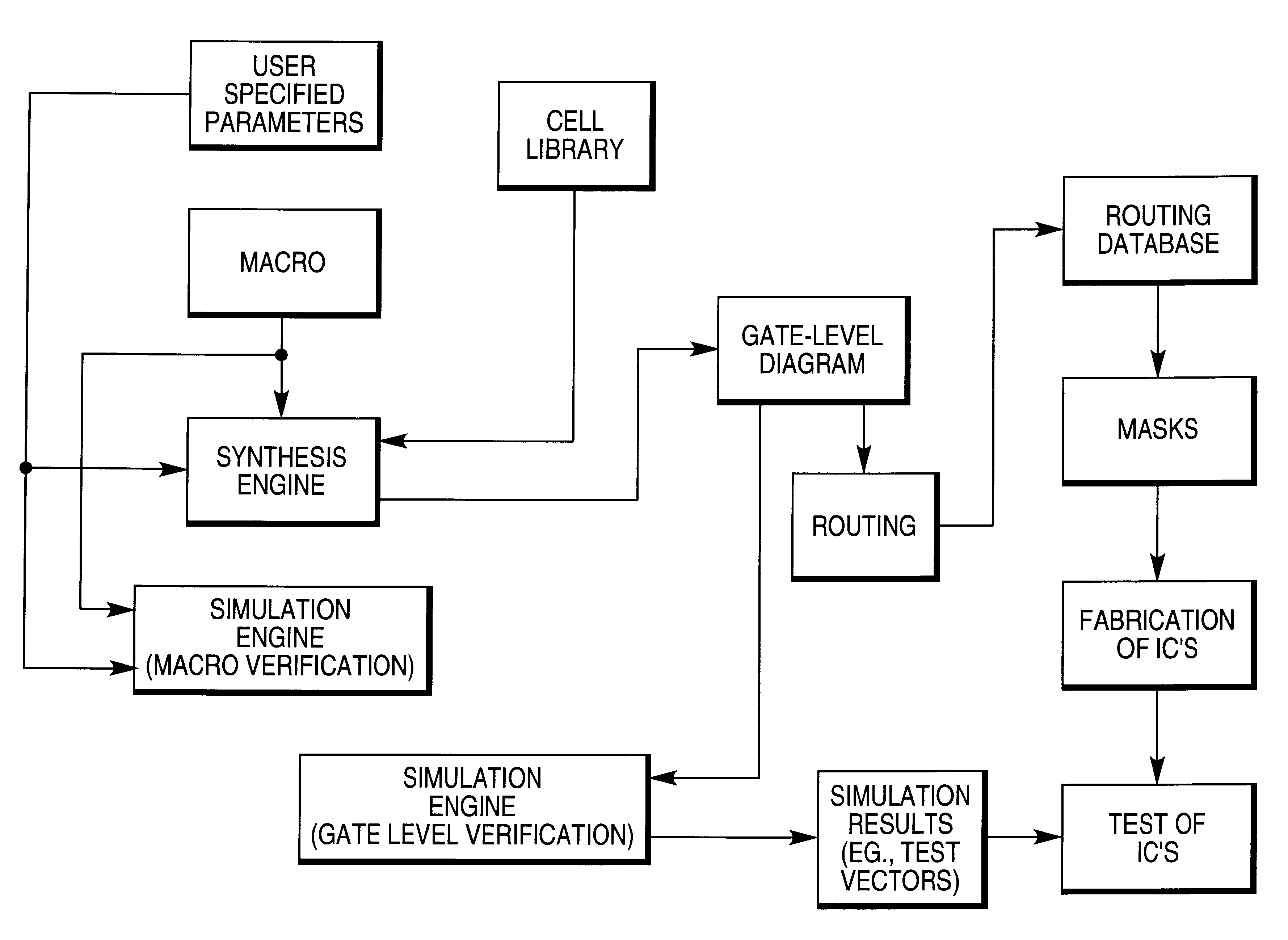
In one form of the invention, configurable device adapters are provided. The invention provides circuitry, for a particular type or class of device, which adapts the device to a bus. The individual circuitry for each device can be optimized, or "tuned," within certain parameter limits. A general purpose macro is used in conjunction with user specified parameters for a particular device, to generate a customized, or tuned, device adapter design based on such user specified parameters. Accordingly, a large degree of specific design information that would otherwise have to be manually provided by a user is automatically generated by use of the general purpose macro. The macro embodies a high degree of configuration to meet a wide variety of device support requirements. The user can thus configure the macro in such a way as to be tuned to meet particular system performance requirements.
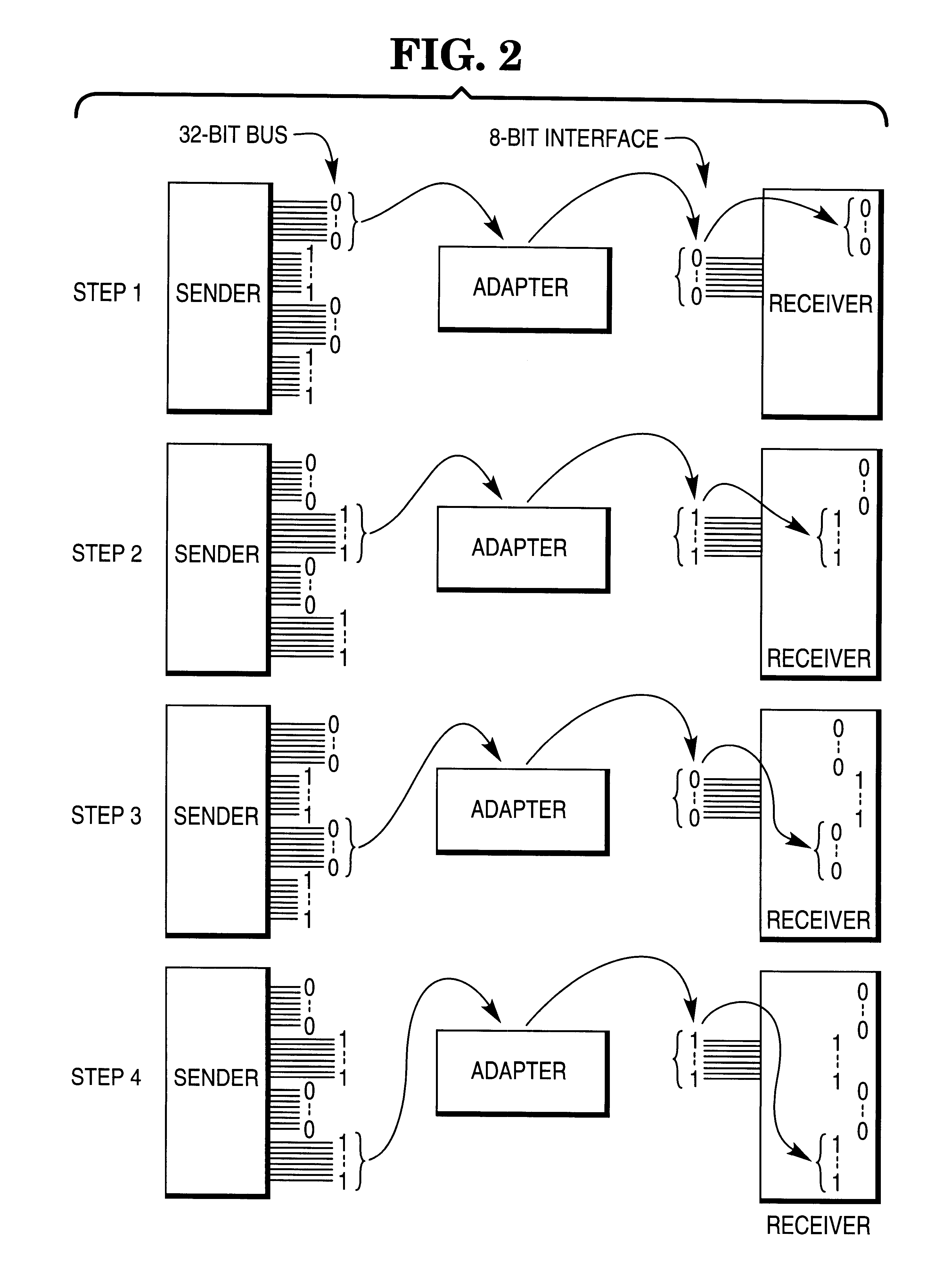
FIG. 2 illustrates a simple way of transferring data from 32-bit data bus to a receiver having an 8-bit data interface.
1. A bus 12 is shown. Typically, the bus is a system bus in a micro-computer. Devices 14 do not directly communicate with the bus. Instead, the devices 14 communicate with a device adapter 16. The invention provides a method and apparatus for generating a device adapter 16 which allows a given device 14 and the bus 12 to communicate with each other. The configurable macro has the flexibility of generating a device adapter that supports multiple devices all of the same type or class, or that supports multiple, dissimilar types of devices. Alternatively, and as a further exemplification of the flexibility of the present invention, the macro can be configured to provide separate device adapters for each interconnecting device (whether similar or dissimilar).
As a single load, the device adapter simplifies some overhead which the bus would otherwise incur.
Further, because of particular characteristics of the device adapter, to be discussed later, certain features of the buffers can be changed, without requiring alteration of other circuitry within the device adapter.

Problems solved by technology

However, device adapters do not necessarily result in optimal matching to a particular device, as will be explained.
However, to allow them to do so would result in confusion.
Further, a device interface to a bus does not operate in isolation: if the device and bus attain the highest possible speed between themselves, it is possible that this speed was obtained at a cost to some other components or devices.
However, under this scenario, the processor becomes unavailable for other tasks while tending the printer.
Thus, while throughput of printed data is very high, other tasks have been brought to a standstill.
Thus, in fact, during the full-attention printing, the processor will be spending idle time while the printer prints.
However, a problem with this approach is immediately apparent.
This approach is inefficient from the Sender's view.
It should now be apparent that there are numerous design constraints which exist and trade-offs which are made when attaching a device to a bus.
When designing an adapter to allow such attachment, hereinafter a device adapter, these design constraints and trade-offs result in a time consuming design effort for a particular type or class of device(s).
When a subsequent type or class of device(s) is to attach to this bus, a similar intensive design effort is required to create a device adapter for this new device.

Method used


Image

  • Tunable architecture for device adapter
  • Tunable architecture for device adapter
  • Tunable architecture for device adapter

Examples


Embodiment Construction

The microfiche appendix submitted with this application contains a computer listing for the software (hereinafter called a macro) used in creating and generating a configurable device adapter. The macro requires a VHDL compiler. VHDL compilers are commercially available. VHDL is an acronym referring to VHSIC Hardware Description Language. VHSIC is an acronym referring to Very High Speed Integrated Circuit.

Applicants have used a commercially available VHDL compiler known as V-System VHDL Simulator and Compiler Platform Revision 2.5, available from Model Technology, located Beaverton, Oreg.

To design a customized device adapter, the macro is used in two different ways, namely, (1) in synthesizing a gate-level logic diagram, and (2) in simulating the circuit.

Synthesis

To perform synthesis, a user does the following:

1. The user specifies the following parameters:

The width of the device interface (e.g., 8, 16, or 32 bits).

The address size (i.e. number of bits) of the device interface.

The d...


PUM


Abstract

A method and apparatus for producing an electronic circuit which allows a device to be connected to a bus, such as a system bus in a computer. The invention accepts user specified parameters for configuring a device adapter which interfaces the device to the bus, and thereafter generates a customized device adapter based on such user specified parameters. By using a common design macro, which is programmable, a user can easily specify and generate custom device adapters for a plurality of dissimilar devices to be connected to the bus. A resulting adapter architecture allows for multiple, dissimilar devices to interface to a computer bus with a single device adapter integrated circuit or card.

Description

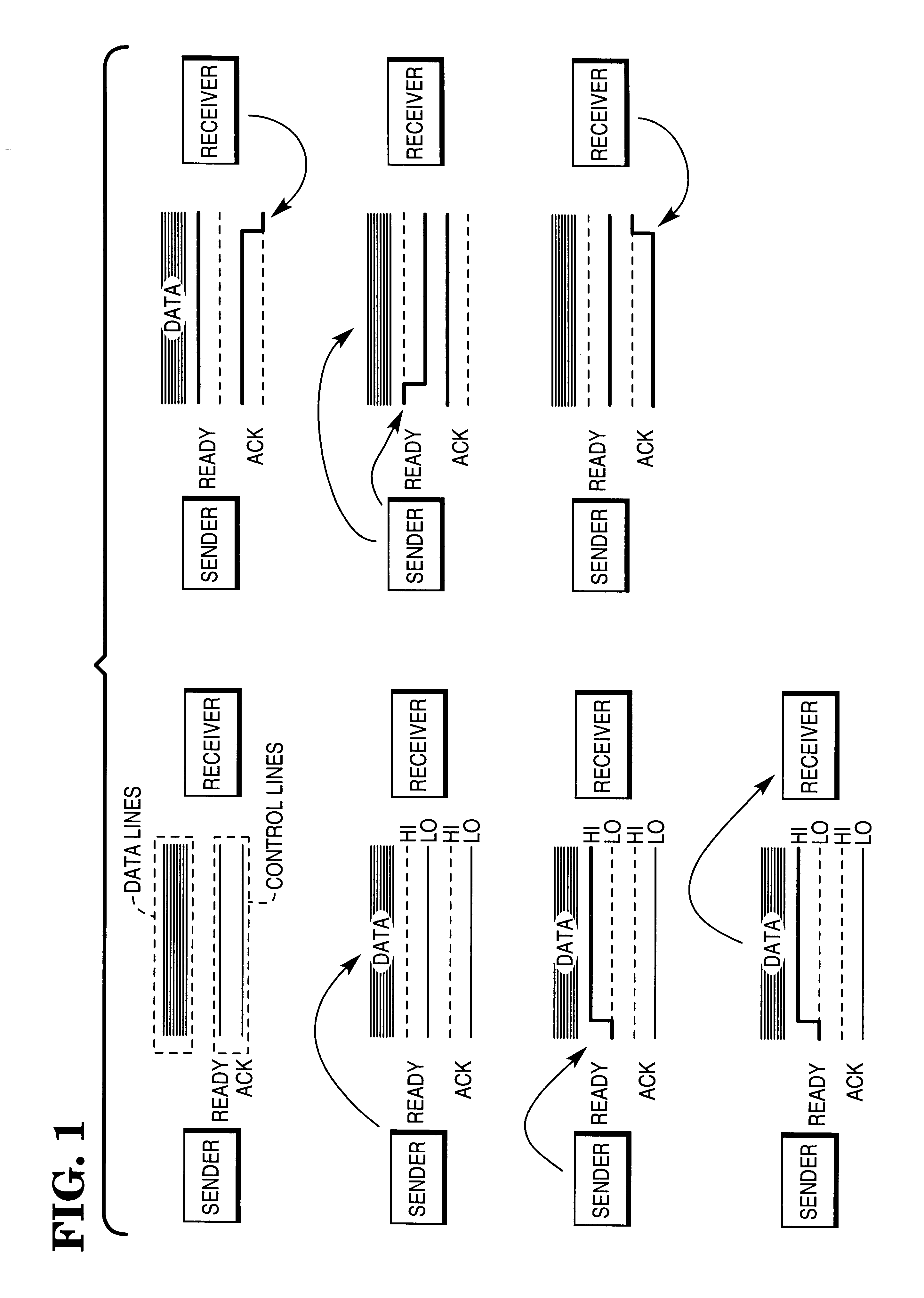
A MICROFICHE APPENDIX is part of this patent. It includes six (6) fiche with four hundred and four (404) frames.The invention concerns configurable device adapters for connecting dissimilar types of devices to a data processing system bus. The invention can optimally match the bus to each device, and for this reason the invention is called "tunable."This discussion will first explain a highly simplified data bus, and then illustrate how the simplified bus has evolved into a vast array of different types of data busses.Different types of devices can generally be connected to a bus by different types of device adapters. However, device adapters do not necessarily result in optimal matching to a particular device, as will be explained.FIG. 1 illustrates a highly simplified example of data transfer over a bus. The transfer sequence is the following, beginning at the top left part of the Figure:1. The Sender places data onto the Data Lines, as indicated.2. The Sender pulls a Ready line H...

Claims


Application Information

Patent Timeline
Patent Type & Authority Patents(United States)
IPC IPC(8): G06F17/50
CPCG06F17/5045G06F30/30
Inventor AVERY, JAMES M.ISENBERG, WILLIAM D.
Owner TAIWAN SEMICON MFG CO LTD
Learn More