
Method for adding and encoding error correcting codes and its device and method for transmitting data having error correcting codes added

a technology of error correction and error correction code, applied in the field of adding and encoding error correction code and its device and method for transmitting data having error correction code added, can solve the problems of exceeding the error correction ability and receiving transmission signal cannot be properly decoded

Inactive Publication Date: 2001-09-11
SONY CORP
View PDF3 Cites 182 Cited by
  • Summary
  • Abstract
  • Description
  • Claims
  • Application Information

AI Technical Summary

Problems solved by technology

Thus, in such digital satellite broadcasting system, if many errors generate during transmission and the C / N ratio lowers below the prescribed threshold value, a problem such that received transmission signals cannot be properly decoded has been occurred by unfortunately exceeding the error correction ability.

Method used


Image

  • Method for adding and encoding error correcting codes and its device and method for transmitting data having error correcting codes added
  • Method for adding and encoding error correcting codes and its device and method for transmitting data having error correcting codes added
  • Method for adding and encoding error correcting codes and its device and method for transmitting data having error correcting codes added

Examples


first embodiment

(1) First Embodiment

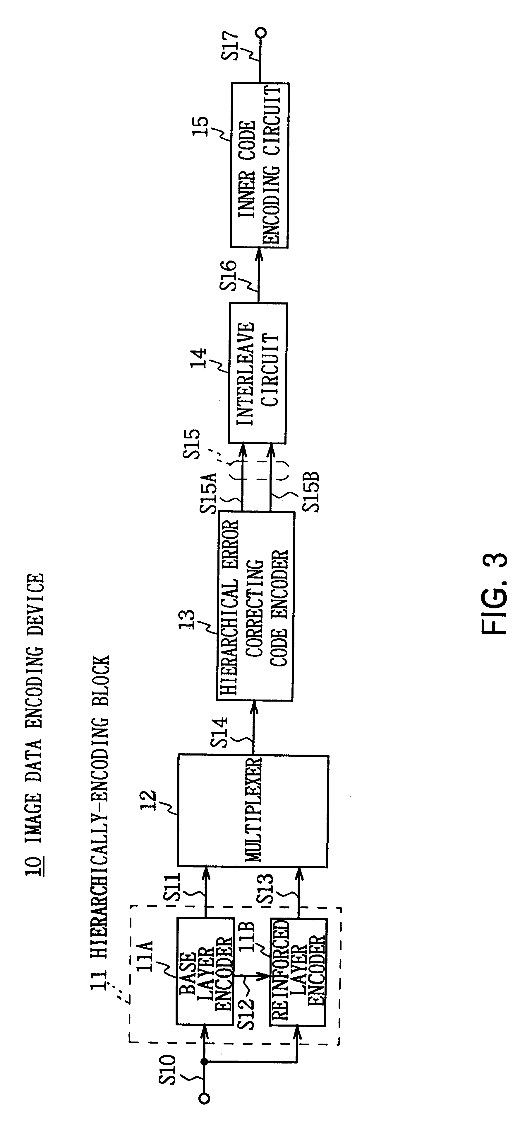
Referring to FIG. 3 generally shows an image data encoding device 10. The device 10 is composed of a hierarchically encoding block 11, a multiplexer 12, a hierarchical error correcting code encoder 13, an interleave circuit 14 and an inner code encoding circuit 15. The image data encoding device 10 inputs HDTV (High Definition Television) image data S10 supplied from a hard disk or the like into the hierarchically-encoding block 11.

The hierarchically-encoding block 11 has a base layer encoder 11A and a reinforced layer encoder 11B. The HDTV image data S10 is supplied to the base layer encoder 11A and the reinforced layer encoder 11B to be divided into two image data having different resolutions for respective encoding (so-called hierarchical encoding).

The base layer encoder 11A thins out desired picture elements from among picture elements of the HDTV image data S10 and generating SDTV (Standard Definition Television) image data. The base layer encoder 11A compre...

second embodiment

(2) Second Embodiment

FIG. 7 in which the same reference number is added to the corresponding part of FIG. 3 shows an image data encoding device 30 according to a second embodiment. This device 30 is configured similarly to the image data encoding device 10 according to the first embodiment except for the configuration of an interleave circuit 31.

The interleave circuit 31 sequentially writes the base layer parity added data forming the base layer coded data S15A and the reinforced layer parity added data forming the reinforced layer coded data S15B into one memory in desired order. When reading data out, the interleave circuit 31 rearranges the data by reading the data out in different order from write sequence, and supplies this to the inner code encoding circuit 15 as interleave data S50.

That is, as shown in FIG. 8A, the interleave circuit 31 sequentially writes in desired number of the base layer parity added data and the reinforced layer parity added data in desired order from th...


PUM


Abstract

A method for encoding error correcting codes to generate plural coded data having different error correction ability according to significance. An error correcting code having different code length is added to a fixed length of input data according to the significance of the input data (S14). The error correcting codes added which have different error correction ability corresponding to its code length are encoded to generate coded data having different packet length according to the code length of the error correcting code. Thus, plural coded data (S15A and S15B) which have different error correction ability according to significance can be generated. Thereby, even if a quality of transmission system deteriorates when the above coded data is transmitted, the coded data having high error correction ability can be surely decoded.

Description

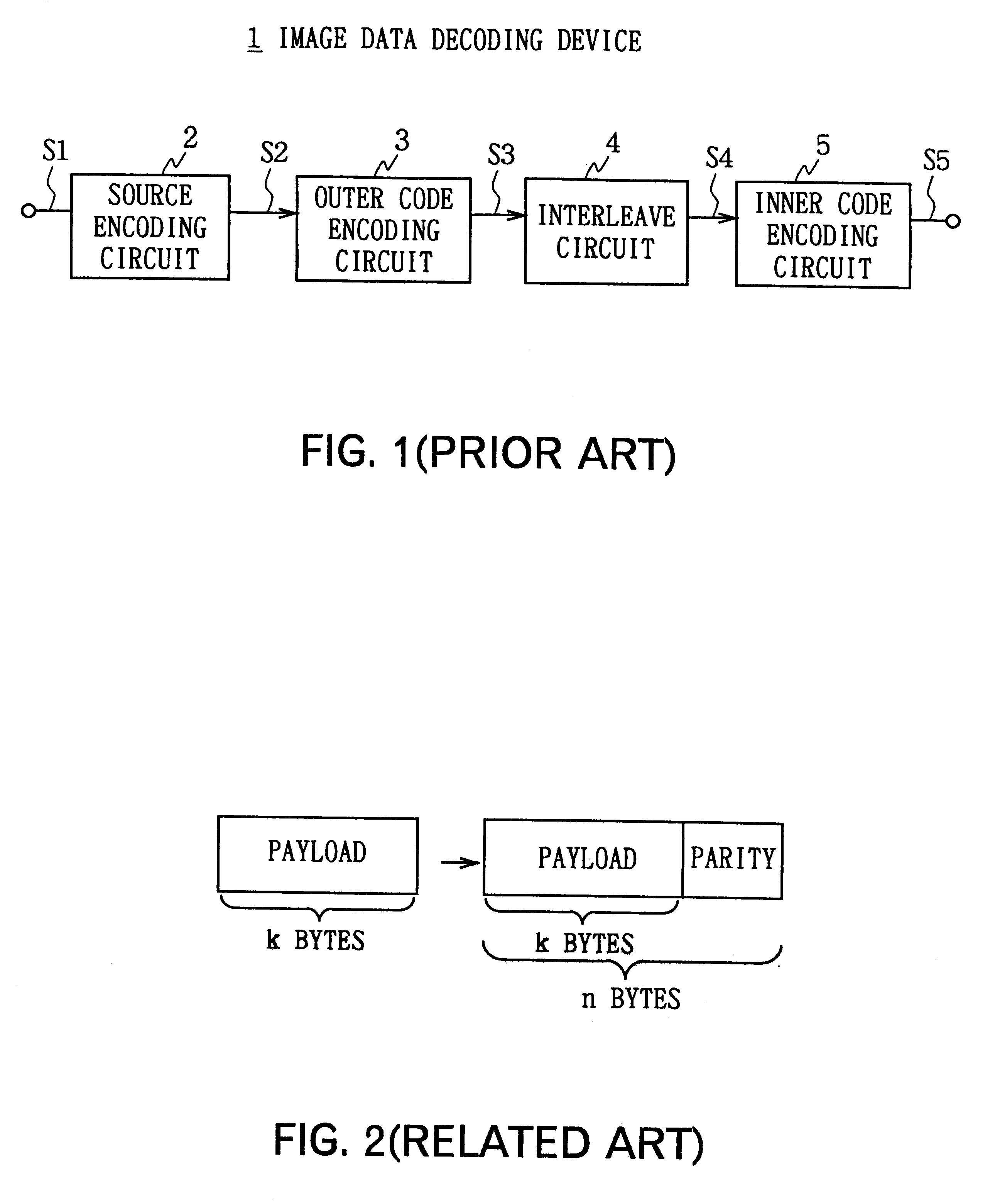
The present invention relates to a method for encoding error correcting codes and its device and method for transmitting data having error correcting codes added, and is applicable to a digital satellite broadcasting system, for example.DESCRIPTION OF THE RELATED ARTHeretofore, this type of digital satellite broadcasting system compressively encodes image data of plural programs using an MPEG (Moving Picture Experts Group)2 system as a compression-encoding system for image data, and then multiplexes them into one bit stream for transmission. At this time, this digital satellite broadcasting system adds error correcting codes to compressively-coded image data and then transmits it on a transmitting side, and decodes the error correcting codes on a receiving side to correct errors generated in the process of transmission. Thereby, the digital satellite broadcasting system can properly restore a transmission signal on the receiving side even if the carrier-to-noise ratio (C / N ratio) of...

Claims


Application Information

Patent Timeline
IPC IPC(8): H04L1/00H04N19/00H03M13/00H03M13/27H04N19/102H04N19/162H04N19/187H04N19/30H04N19/33H04N19/46H04N19/65H04N19/67H04N19/70H04N19/85H04N19/88H04N19/89
CPCH04L1/0041H04L1/007H04L1/0065H04L1/00
Inventor SHIOMOTO, SHOJI
Owner SONY CORP
Learn More