
Scratch protection in tape data storage system

a tape data and storage system technology, applied in the direction of digital signal error detection/correction, instruments, recording signal processing, etc., can solve the problems of tape data loss, tape scratches, tape corruption at the edges,

Inactive Publication Date: 2001-08-28
HEWLETT-PACKARD ENTERPRISE DEV LP
View PDF7 Cites 72 Cited by
  • Summary
  • Abstract
  • Description
  • Claims
  • Application Information

AI Technical Summary

Benefits of technology

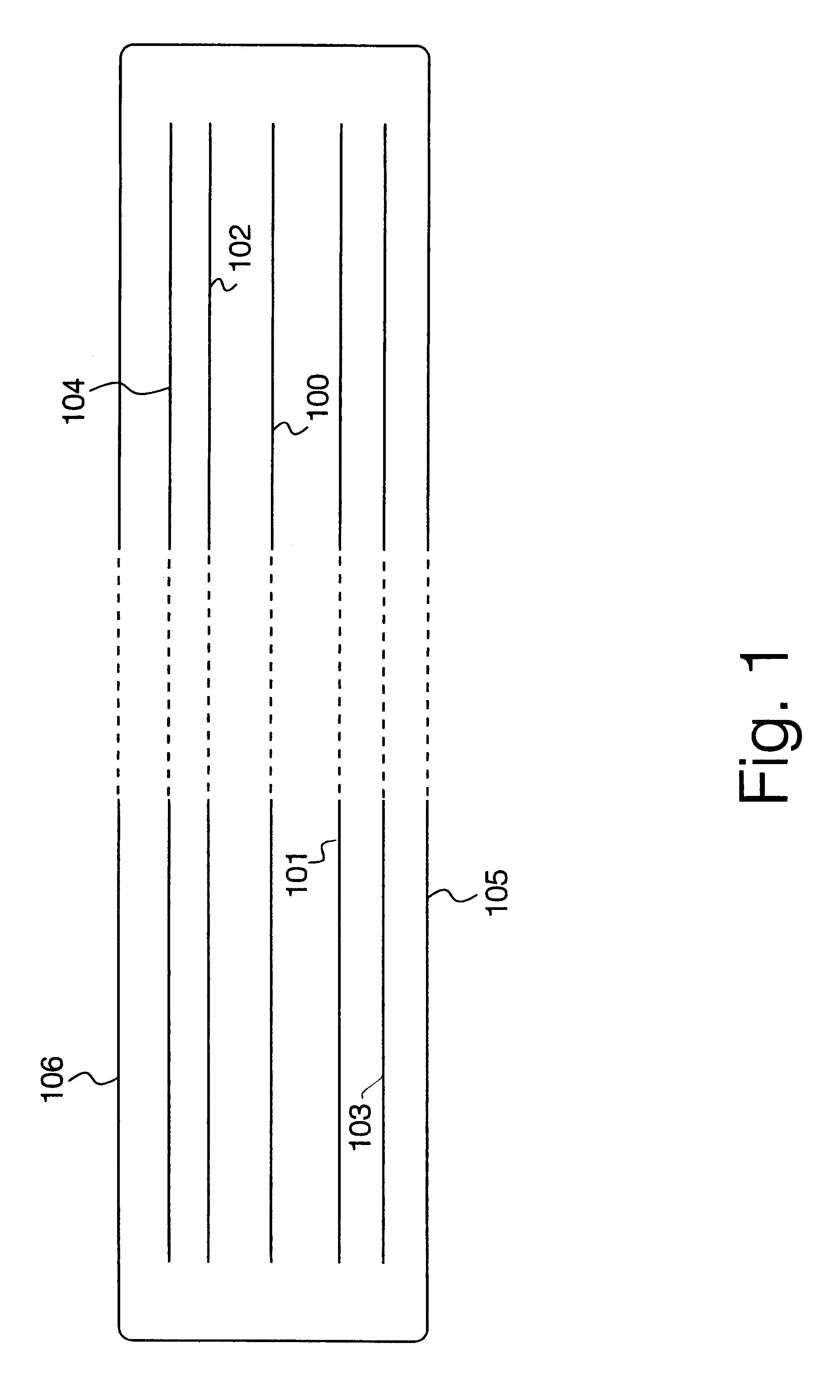
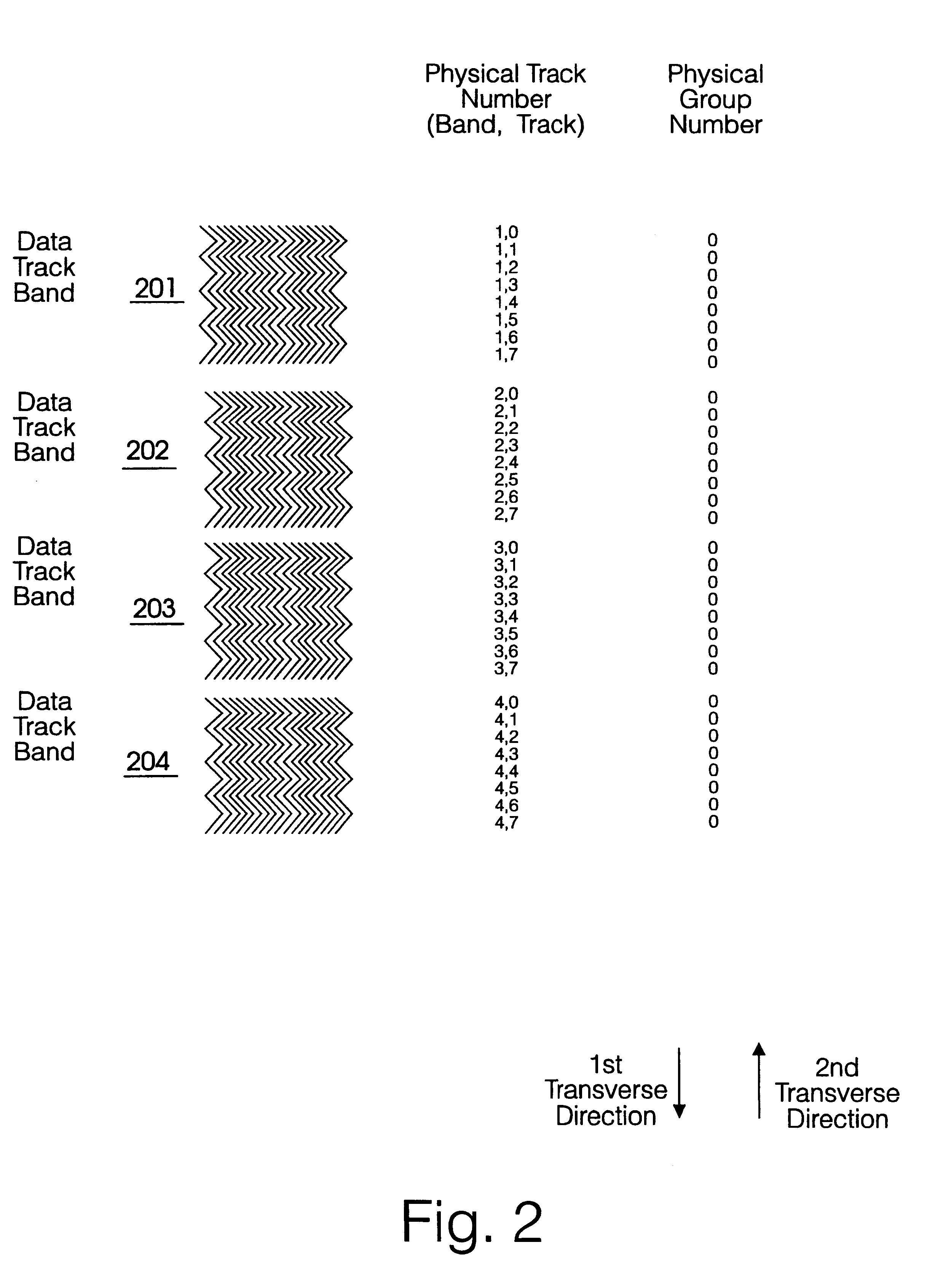
Suitably, a plurality of bytes of a second codeword are distributed substantially uniformly over an area of tape occupied by a plurality of recorded data frames. By distributing bytes of a second codeword substantially diagonally across a length of the tape and by spreading out the bytes substantially uniformly over a length occupied by an area of the tape corresponding to the plurality of the recorded data frames, improved protection against longitudinal scratches in a direction parallel to a length of the tape, and transverse scratches in a direction normal to a length of the tape may be obtained.

Problems solved by technology

Such corruption may occur at the edges of the tape due to non-uniform coating of the tape with magnetic material, or due to variations in alignment of the tape with the read / write head.
However, as data density is increased and tape sizes become smaller, loss of data due to tape damage caused by tape stretching, or scratching of the tape becomes more problematic as any such damage may obliterate larger amounts of data.

Method used


Image

  • Scratch protection in tape data storage system
  • Scratch protection in tape data storage system
  • Scratch protection in tape data storage system

Examples


Embodiment Construction

There will now be described by way of example the best mode contemplated by the inventors for carrying out the invention. In the following description numerous specific details are set forth in order to provide a thorough understanding of the present invention. It will be apparent however, to one skilled in the art, that the present invention may be practiced without using these specific details. In other instances, well known methods and structures have not been described in detail so as not to unnecessarily obscure the present invention.

Specific methods according to the present invention as described herein are aimed at magnetic tape recording devices having a substantially static read / write head in which an elongate tape wound between first and second reels is drawn past the head at relatively high speed, for example of the order of 3 meters per second. Reading and writing of data onto the tape may be carried out in both forward and reverse pass directions of the tape relative to...


PUM


Abstract

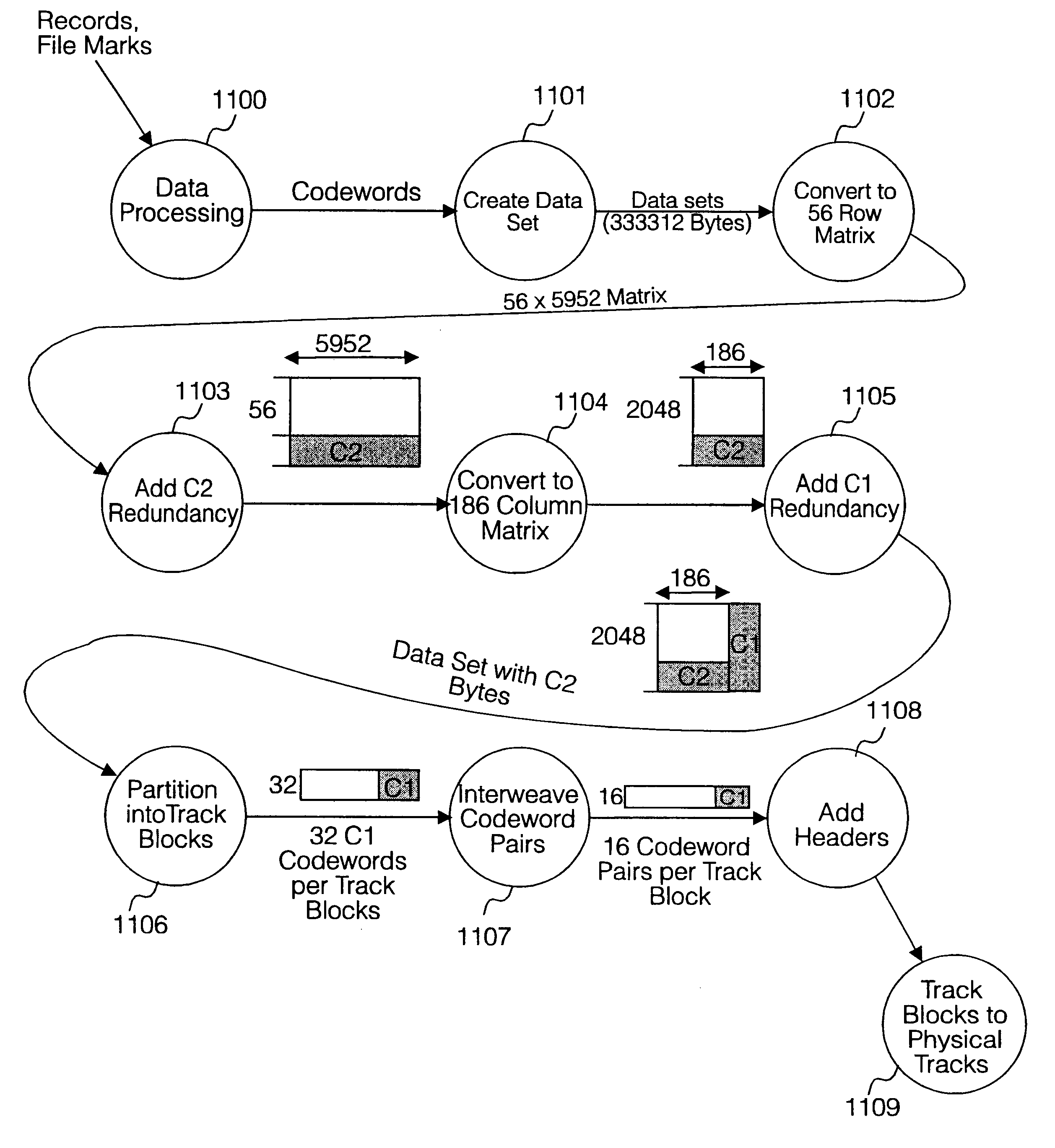
A method of redundancy coding of user data received from a host apparatus and storage of said coded data on a magnetic tape data storage medium comprises inputting a byte stream of user data into a buffer and assembling a plurality of data sets in the buffer; for each data set assembling a data set into a two-dimensional data array and (1103) applying a second redundancy coding algorithm (C2 parity) to the two-dimensional data set in a second dimension; applying (1105) a first redundancy coding (C1 parity) algorithm to the second redundancy coded data array in a first dimension to form a two-dimensional data frame having second and first redundancy coding in respective second and first dimensions, the two-dimensional data frame comprising a plurality of rows, each row comprising a first codeword and a plurality of columns, each column comprising a second codeword; partitioning the two-dimensional data frame into a plurality of logical track blocks (1106) each comprising a plurality of first codewords; and recording (1110) each logical track block to a corresponding respective physical track on the magnetic tape data storage medium. Redundancy coding of a data frame is distributed across a plurality of other data frames along the tape, and redundancy bytes of each data frame are distributed across a plurality of data tracks. Redundancy coding may be distributed diagonally across a width of the tape. Data obliterated due to damage to individual physical recorded tracks or sections of tracks on the tape may be recovered from redundant coding data distributed across other adjacent parallel physical tracks on the tape.

Description

The present invention relates to a method of redundancy coding for scratch protection in a linear tape data storage device and medium.BACKGROUND TO THE INVENTIONIn order to store digital electronic data it is known to use magnetic tape cartridges comprising a pair of reels, which are inserted into a tape drive unit having a plurality of read / write heads. Typically, such magnetic tape storage devices may be used to back up data generated by a host device, eg a computer, or to store data generated by test or measurement instruments. For example, the conventional SureDrive.RTM. data storage unit manufactured by Hewlett Packard Company is capable of storing 8 GBytes of data on a single cassette cartridge. In the conventional SureDrive series 12000 unit, by including a plurality of cassette cartridges, a data storage capacity 48 Gbytes is achieved in a single compact drive assembly of dimensions of the order of a few tens of centimeters.Conventional tape drive units operate to draw an el...

Claims


Application Information

Patent Timeline
IPC IPC(8): G11B20/18G11B20/12G06F11/10
CPCG11B20/12G11B20/1833G11B2220/916
Inventor BARTLETT, PAUL FREDERICK
Owner HEWLETT-PACKARD ENTERPRISE DEV LP
Learn More