Multi-plate clutch for a motor vehicle

Inactive Publication Date: 2001-08-28
ZF FRIEDRICHSHAFEN AG
View PDF5 Cites 12 Cited by
  • Summary
  • Abstract
  • Description
  • Claims
  • Application Information

AI Technical Summary

Benefits of technology

As a result of this arrangement, each of the intermediate plates and the pressure plates are pressed apart by the spring elements. The springs ensure that a sufficient gap exists between each of the intermediate plates and pressure plates when the multi-plate clutch is in the disengaged state so that the friction facing arranged in the gap can rotate freely. The friction facings are therefore separated particularly reliably from the intermediate plate and pressure plates. Accordingly, the multi-plate clutch according to the invention exhibits particularly low wear.
Heat generated in the multi-plate clutch according to the invention may also be guided away in a simple manner when a housing cover arranged in front of one of the pressure plates has ventilation slits. This contributes to a further reduction of the temperature level inside the clutch and accordingly to a further reduction in wear of the friction facings.
To further reduce the radial dimensions of the multi-plate clutch according to the invention, an internal toothing of the housing engaging in the external toothing of the intermediate plate has recesses in the area of the spring elements.
According to another advantageous development of the invention, the spring elements require no installation space in the radial direction when the spring elements have dimensions corresponding to the radial dimensions of the external toothing of the intermediate plate. Since the external toothing is already present between the intermediate element and the housing, and since a very large number of spring elements can be used in this area, spring tongues with a width corresponding to the external toothing of the intermediate plate can be used without difficulty.

Problems solved by technology

A disadvantage in this known arrangement for a known multi-plate clutch is that the intermediate plate is not reliably separated from the friction facings.
The lack of reliable separation leads to high wear of the friction facings and to an unnecessary heating of the friction facings.
The heat generated in this respect must subsequently be removed from the multi-plate clutch in a costly manner.
Further, the drag torque brought about by the grinding of the friction facings puts a strain on a synchronization device of a transmission arranged downstream.

Method used


Image

  • Multi-plate clutch for a motor vehicle
  • Multi-plate clutch for a motor vehicle
  • Multi-plate clutch for a motor vehicle

Examples


Embodiment Construction

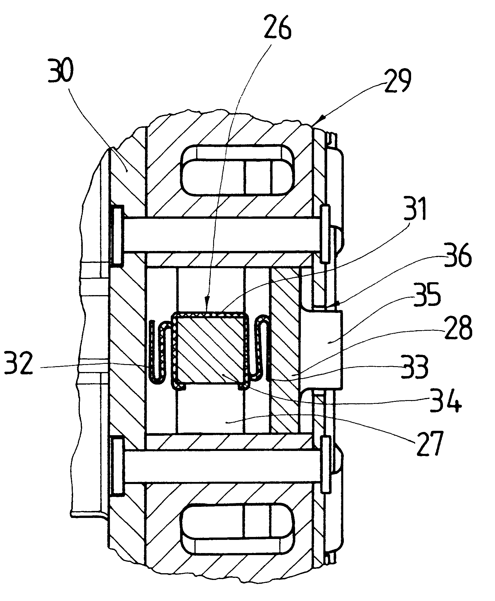
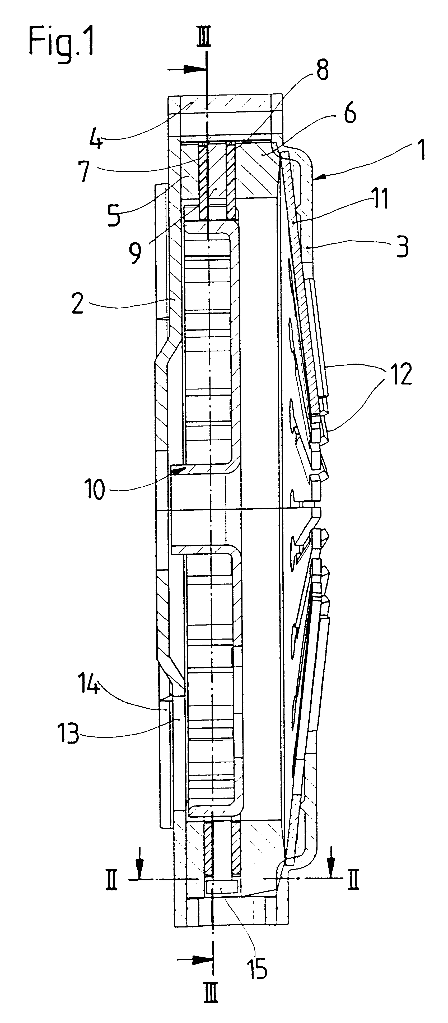
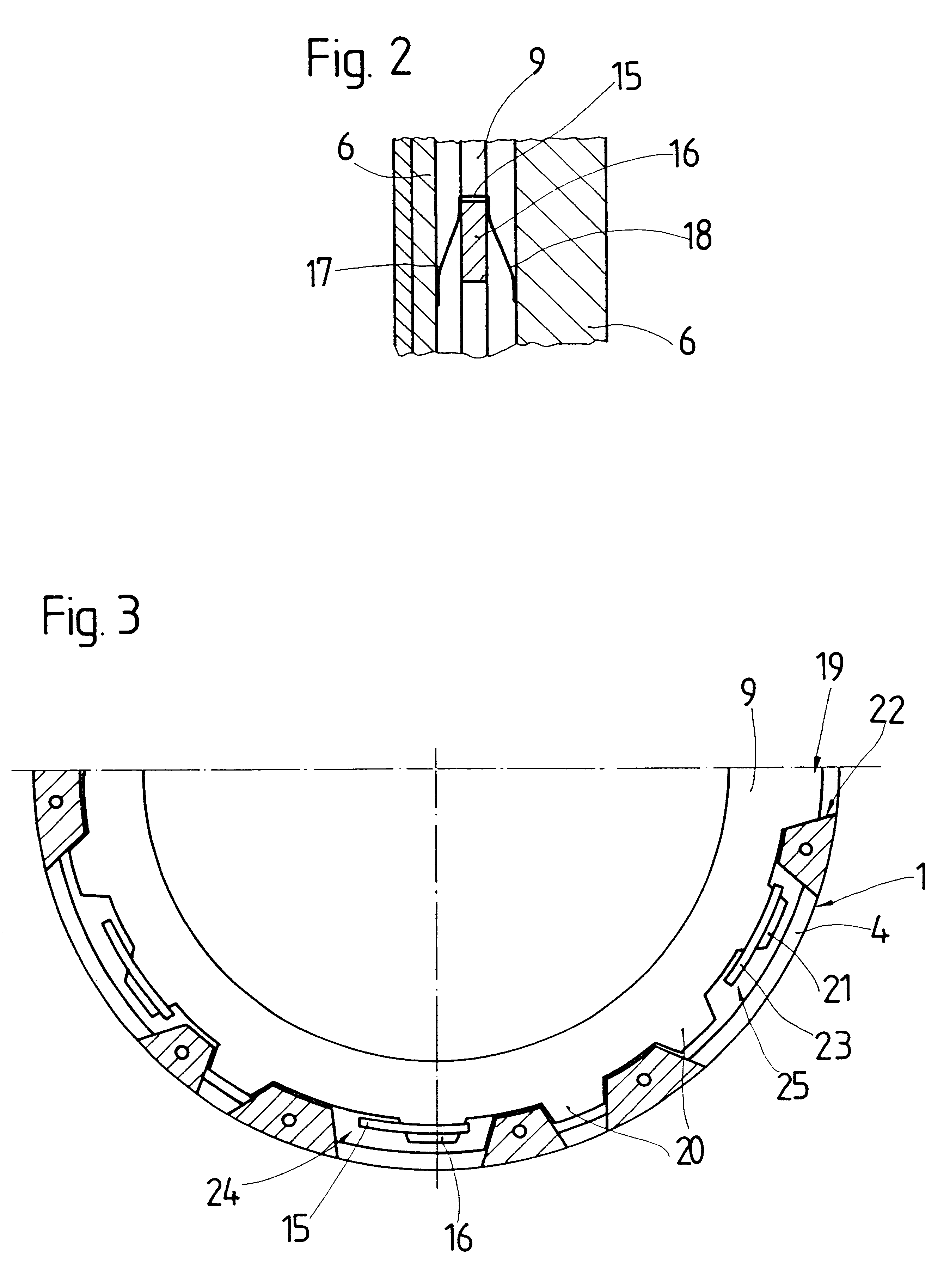
FIG. 1 shows a longitudinal section of a multi-plate clutch 100 according to the invention with a housing 1. The housing 1 includes a housing ring 4 arranged between first and second housing covers 2, 3. First and second pressure plates 5, 6 for pretensioning first and second friction facings 7, 8 toward an intermediate plate 9 are arranged in the housing 1. The intermediate plate 9 and the first and second pressure plates 5, 6 are connected with the housing ring 4 so that they are fixed with respect to rotation relative to the housing ring 4. The first and second friction facings 7, 8 are fastened to a hub 10 so that they are fixed with respect to rotation and axially displaceable relative to the hub 10. The second pressure plate 6 contacts a diaphragm spring 11. The diaphragm spring 11 has venting blades 12 for conveying cooling air through the housing 1 to ventilation slits 13 of the housing cover 2 located opposite the diaphragm spring 11. The housing cover 2 likewise has ventin...


PUM


Abstract

A multi-plate clutch for a motor vehicle has a U-shaped spring element fastened to an intermediate plate for holding adjacent pressure plates at a distance from one another. The intermediate plate is reliably held between the pressure plates. Grinding of friction facings arranged between the intermediate plate and the pressure plates is accordingly minimized. The spring element is arranged in an area of an external toothing of the intermediate plate and therefore does not contribute to an increase in the radial dimensions of the multi-plate clutch.

Description

1. Field of the InventionThe present invention is directed to a multi-plate clutch for a motor vehicle with at least one intermediate plate arranged between friction facings, two pressure plates for pretensioning the friction facings toward the intermediate plate, and a spring element for separating the pressure plates and the intermediate plate from the friction facings.2. Description of the Related ArtMulti-plate clutches are characterized in that they are capable of transmitting high torques. The known multi-plate clutch has a plurality of spring elements arranged radially outside of the intermediate plate for pressing apart the pressure plates. When the pressure plates are spread apart by the spring elements, no transmission of torque should take place between a shaft which is connected with the friction facings so as to be fixed with respect to rotation relative to them and a shaft conlected with the pressure plates.A disadvantage in this known arrangement for a known multi-pla...

Claims


Application Information

Patent Timeline
IPC IPC(8): F16D13/52F16D13/00F16D13/38F16D13/69
CPCF16D13/385F16D13/52F16D2013/706F16D2013/581F16D13/69
Inventor ORLAMUNDER, ANDREAS
Owner ZF FRIEDRICHSHAFEN AG
Why Eureka
Try Eureka