
Method for automatized combustion and combustion apparatus

Inactive Publication Date: 2001-08-14
SWEDISH BIOBURNER SYST
View PDF15 Cites 16 Cited by
  • Summary
  • Abstract
  • Description
  • Claims
  • Application Information

AI Technical Summary

Benefits of technology

The apparatus shall be easy to trim, which i.a. implies that the method of operation of the apparatus shall be such that it readily, through the setting of various parameters in a control program, can be adapted to those conditions which apply in every single case, such as the effect need, the character of the fuel, etc.
The flue gases which are emitted from the combustion apparatus shall at all effect levels only contain product

Problems solved by technology

The main reason for this condition probably is that it is easy to automatize combustion of fuel oil but comparatively difficult to automatize combustion of solid fuel, and it is particularly difficult to automatize solid fuel combustion in order to provide an efficient combustion at all heating effect levels without emission of products with the fuel gases which are harmful to the environment.

Method used


Image

  • Method for automatized combustion and combustion apparatus
  • Method for automatized combustion and combustion apparatus
  • Method for automatized combustion and combustion apparatus

Examples


Embodiment Construction

Main Units of the Combustion Apparatus

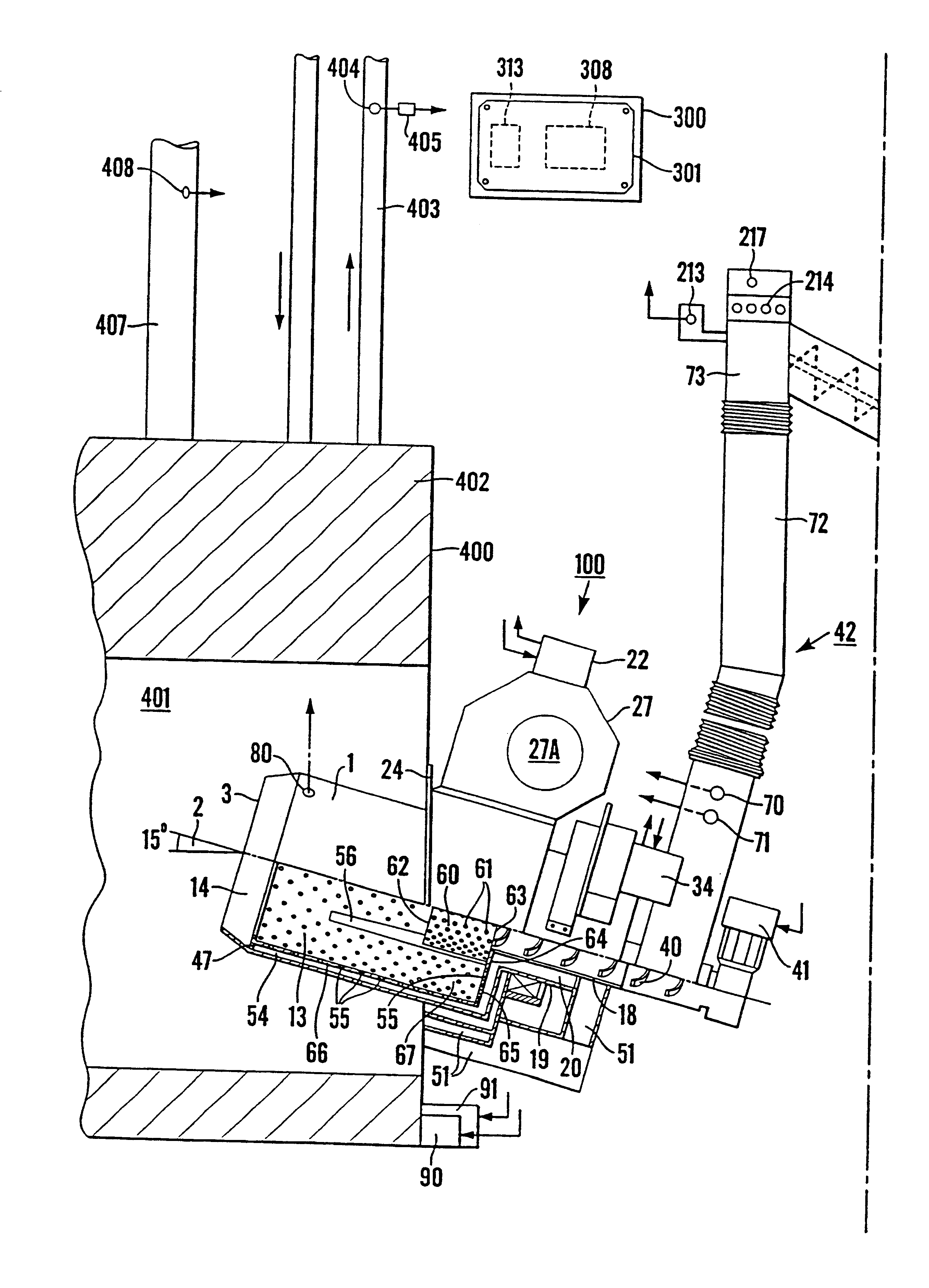
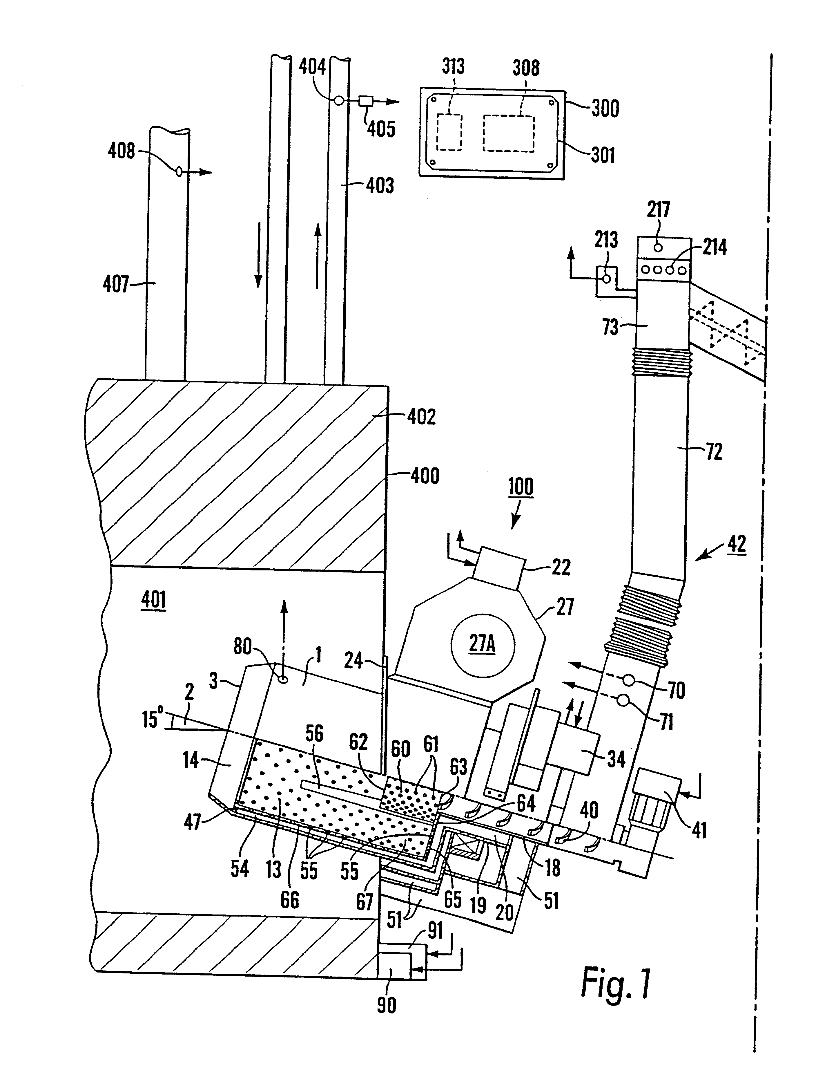
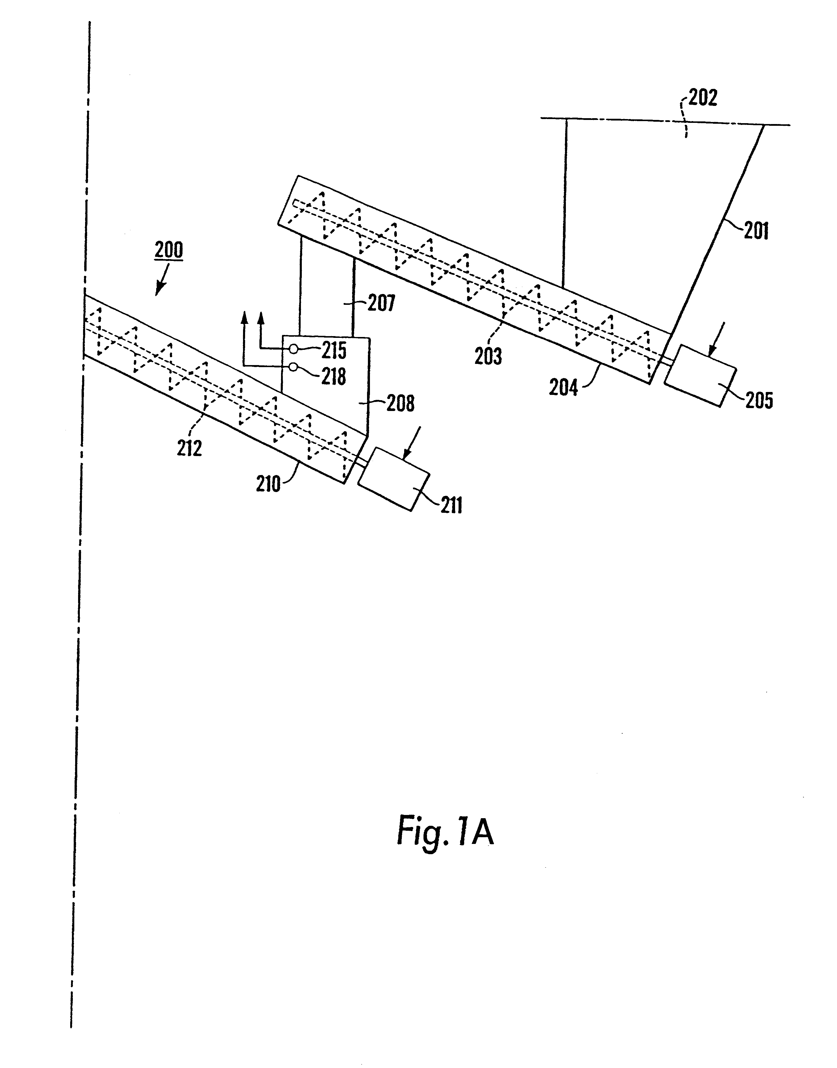
The main units of the combustion apparatus consist of a burner assembly 100, a fuel charge feeder assembly 200, and a control unit 300. The burner assembly 100 is connected to a schematically shown boiler 400, which may be of a conventional kind.

Description of the Burner Assembly 100

In the burner assembly 100 there is included a solid fuel burner or reactor which has the general shape of a vessel, more particularly the shape of a drum. According to the embodiment, the reactor drum 1 is circular-cylindrical and is rotatable about a slightly inclined axis of rotation. It has an outer flange 24 for mounting the whole burner assembly 100 on a boiler door of the schematically shown boiler 400, such that an opening 3 for the combustion gases in the front end of the burner will mount in the combustion chamber 401 of the boiler. The interior of the burner forms a main or primary combustion chamber and an after- or secondary combustion chamber 14.

Other c...


PUM


Abstract

A method for automatized combustion of solid fuel in a combustion apparatus which comprises a burner with a device, which is rotatable about the center axis of the burner for stirring the fuel in the burner which is connected to a boiler and has a feeding-in opening for fuel in the rear end of the burner outside of the boiler and an outlet opening for completely or partly combusted flue gases in the front end of the burner which opens in a combustion chamber inside the boiler which comprises a convection unit, from which a hot water conduit extends, the combustion apparatus also including a fan provided to be driven by a second motor for blowing combustion air into the burner, and a fuel charge feeder for fuel provided to be driven by a third motor.

Description

The invention relates to a method for automatized combustion of solid fuel in a combustion apparatus which comprises a burner with a device, which is rotatable about the centre axis of the burner for stirring the fuel in the burner which is connected to a boiler and has a feeding-in opening for fuel in the rear end of the burner outside of the boiler and an outlet opening for completely or partly combusted flue gases in the front end of the burner which opens in a combustion chamber inside the boiler which comprises a convection unit, from which a hot water conduit extends, said combustion apparatus also including a fan provided to be driven by a second motor, here called fan motor, for blowing combustion air into the burner, and a fuel charge feeder for fuel provided to be driven by a third motor, here called fuel charge feeding motor. The invention also relates to the said combustion apparatus.Solid fuels have a number of significant advantages before fuel oil; they are generally ...

Claims


Application Information

Patent Timeline
IPC IPC(8): F23N1/08F23N1/10F23D1/00F23K3/00F23NF23N5/02F23N5/18F27B7/32F27B7/34
CPCF23B1/32F23B3/00F23N1/102F23K2203/202F23N2039/02F23N2023/08F23N2025/19F23N2033/08F23B30/04F23N2225/19F23N2223/08F23N2239/02F23N2233/08
Inventor MAGNUSSON, JAN
Owner SWEDISH BIOBURNER SYST
Learn More