
Device for altering the angle between the shaft and the head of a golf club

a golf club and angle adjustment technology, applied in the field of golf clubs, can solve the problems of significantly affecting the score of golfers, affecting the accuracy of ball impact, and conventional golf club putters that do not provide any easy way of adjusting the angle between shaft and head, so as to achieve the effect of simple removal and replacemen

Inactive Publication Date: 2001-08-07
NIRVANA GRP L L C THE
View PDF10 Cites 132 Cited by
  • Summary
  • Abstract
  • Description
  • Claims
  • Application Information

AI Technical Summary

Benefits of technology

It is therefore a principal object of the present invention to provide a golf club having an insert mechanism designed to provide alternative angles between the golf club shaft and the golf club head by simple removal and replacement of the insert mechanism.

Problems solved by technology

Depending upon the golfer's swing mechanics and his or her stance and body dimensions, the angle between a golf club shaft and the ball hitting head to which it is attached can have a significant degree of variation and such variation can drastically affect the accuracy of ball impact and thus significantly impact a golfer's score.
Yet the vast majority of conventional golf club putters do not provide any easy way of adjusting the angle between shaft and head without bending the hosel or neck of the putter.
Unfortunately, the Applicants know of no existing golf club putter which provides for easy and convenient modification of lie angle by simple mechanical adjustment at any time the golfer wishes to alter his or her putting stroke or simply to experiment for achieving greater accuracy in the most significant part of the game.

Method used


Image

  • Device for altering the angle between the shaft and the head of a golf club
  • Device for altering the angle between the shaft and the head of a golf club
  • Device for altering the angle between the shaft and the head of a golf club

Examples


Embodiment Construction

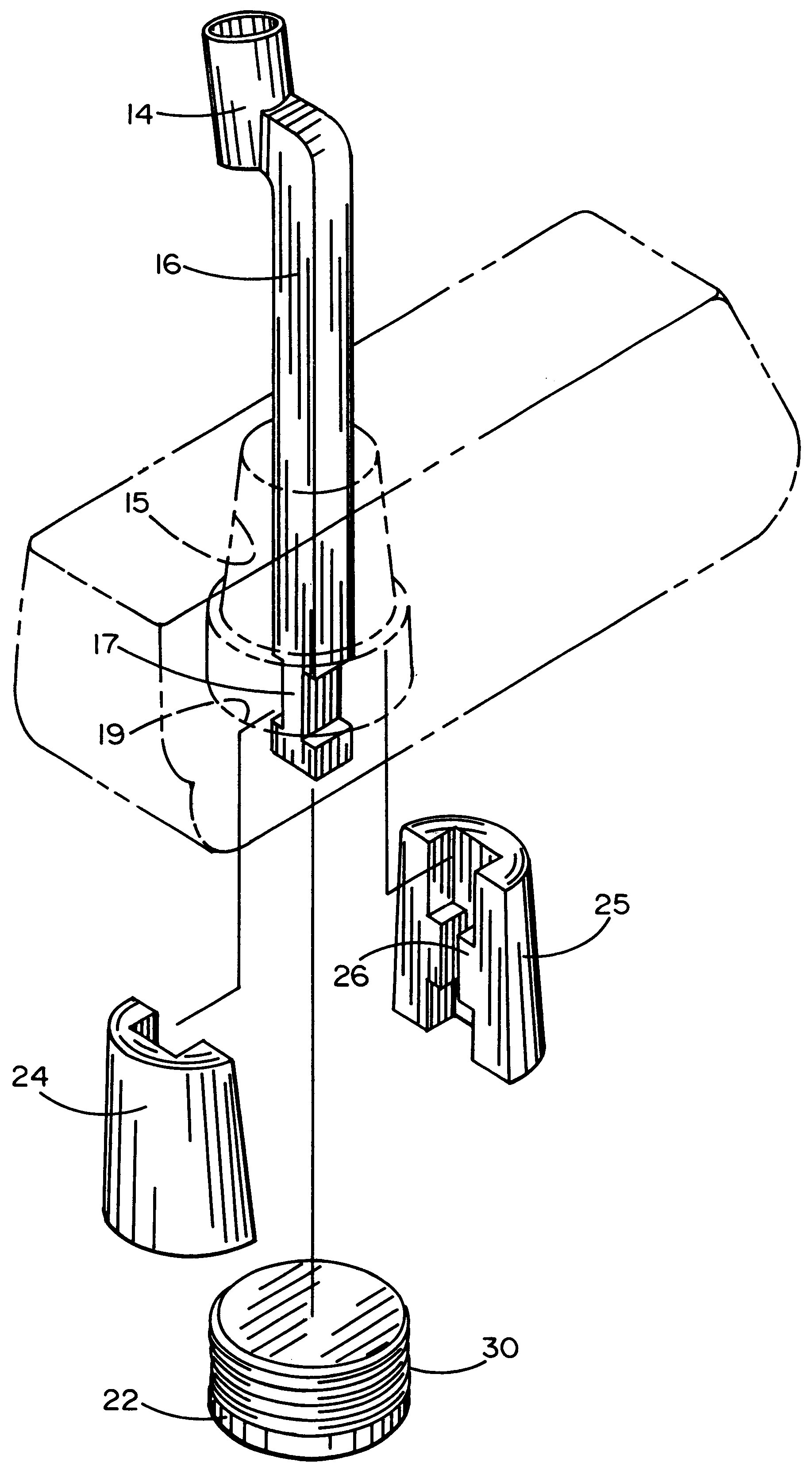
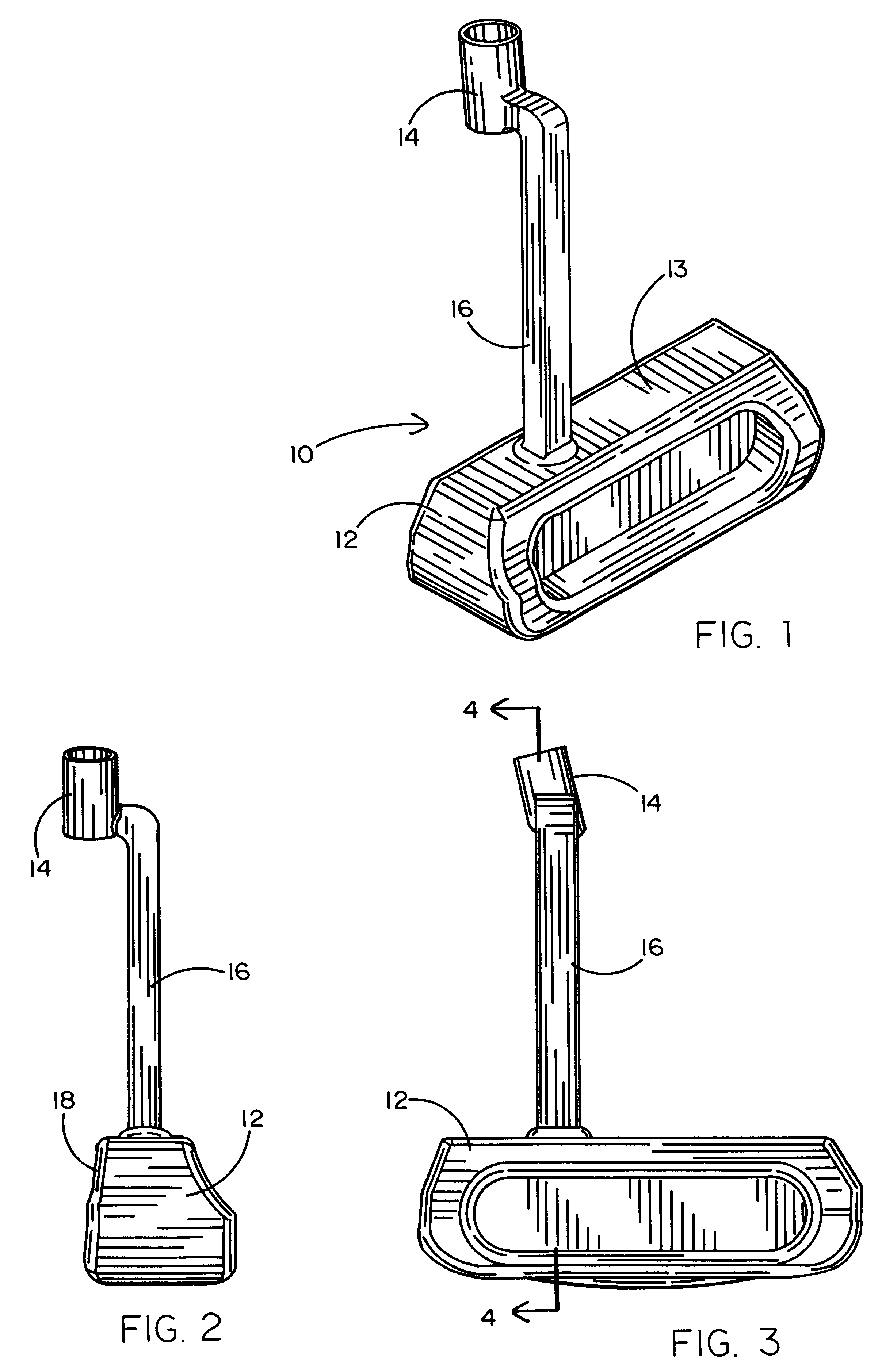
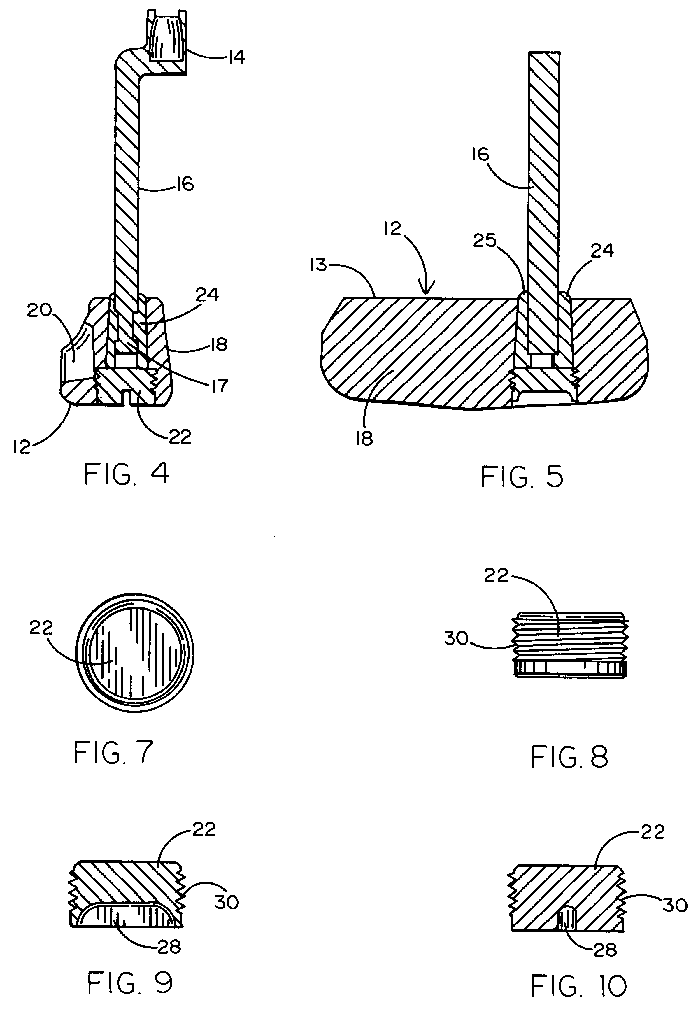
Referring to the accompanying figures, it will be seen that a putter head 10 employing the present invention, comprises a ball striking portion 12 having a face 18, a shaft receptacle 14 and a hosel 16 for connecting the shaft (not shown) to the putter head. As seen best in FIGS. 4, 5 and 6, the putter head has a tapered aperture 15 and a threaded recess 19. The hosel 16 extends into the tapered aperture from the upper surface 13 of the ball striking portion 12. The hosel 16 comprises an insert shank 17 which, as seen in FIG. 6, has a reduced lateral dimension over a short portion of the hosel length. The tapered aperture 15 is shaped to receive a pair of insert members 24 and 25 which have generally a semi-conical-frustum configuration and which in combination form a full conical frustum with a hosel slot 26 therebetween. As seen further in FIGS. 4, 5 and 6, the hosel slot 26 is configured to receive the hosel shank 17 and for trapping the shank and thus the entire hosel 16. A swag...


PUM


Abstract

A device for altering the angle between the shaft and the head of a golf club. The preferred embodiment of the invention utilizes a plurality of inserts which are configured to be inserted into a tapered hole in the golf club head for receiving a shaft or a hosel for mating with the shaft. Each such insert is designed to provide a different angle between head and shaft so that the golfer merely selects one of the plurality of inserts which will be best for his or her hitting accuracy. The inserts are positioned in the club head in such a way as to create a swaging of the insert into the club head and the insert onto the shaft tip. Swaging is the interference fit of two components with two or more surfaces that are forced together in a locking condition, for instance a tapered pin into a tapered hole. A swaging screw is utilized to drive the insert into a tapered swage condition with the club head and thus squeeze onto the shaft to ensure a strong bond without utilizing an adhesive. The disclosed embodiment relates to a golf club putter, but other golf clubs, such as metalwood head golf clubs would employ the invention as well.

Description

1. FIELD OF THE INVENTIONThe present invention relates generally to the field of golf clubs and more specifically, to golf clubs wherein an insert is received in the golf club head and mates with the golf club shaft and wherein the insert may be removed and replaced to provide different relative angles between the head and the shaft.2. BACKGROUND ARTAn important factor in the performance of a golfer on the course is the geometry of the clubs used by the golfer. Depending upon the golfer's swing mechanics and his or her stance and body dimensions, the angle between a golf club shaft and the ball hitting head to which it is attached can have a significant degree of variation and such variation can drastically affect the accuracy of ball impact and thus significantly impact a golfer's score. Perhaps no golf club has more impact on overall score than the putter. In a typical round of golf of eighteen holes, about half the score is attributable to putting strokes. Thus it would not be un...

Claims


Application Information

Patent Timeline
Patent Type & Authority Patents(United States)
IPC IPC(8): A63B53/02
CPCA63B53/02A63B2053/023A63B2053/021A63B53/021A63B53/023A63B60/00
Inventor DYER, ALONZO J.
Owner NIRVANA GRP L L C THE
Learn More