
Video and audio transmission apparatus for vehicle surveillance system

a vehicle surveillance and video and audio transmission technology, applied in the field of video and audio transmission apparatus for vehicle surveillance systems, can solve the problems of difficult or impossible operation for operators, the inability to use mirrors to enable drivers to see certain areas around the vehicle, and the inability to view the area directly behind or underneath a semi-trailer system, etc., to achieve the effect of enhancing such monitoring

Inactive Publication Date: 2001-07-10
H V TECH
View PDF17 Cites 491 Cited by
  • Summary
  • Abstract
  • Description
  • Claims
  • Application Information

AI Technical Summary

Benefits of technology

It is a further object of the present invention to provide a system that enables an operator of a motor vehicle to view and hear the sounds from a plurality of locations surrounding the motor vehicle.
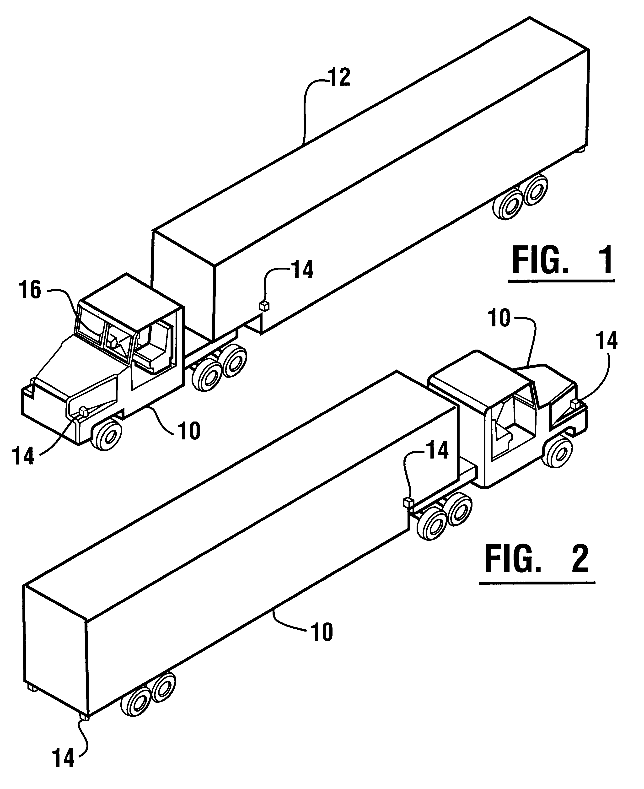
Further embodiments of the invention may include audio-video transmission modules for monitoring the interior spaces of a trailer or bus. This may for example enable an operator of a motor vehicle to view the condition of an animal or livestock being carried in a trailer. It also had the potential for indicating when vandals are attempting to break into a trailer parked either in a rest area or in traffic. The modules can be used to monitor the activities of passengers on a bus. Monitoring may be accomplished from another area or vehicle that is not physically connected to the vehicle being monitored. The remote power source capabilities of the audio-video transmission modules also enable security forces within a facility that handles semi-trailers to monitor activity in the interior of a plurality of trailers. Such monitoring may include the detection of vandalism as well as fires or explosions. To further enhance such monitoring, the audio-video transmission module of the present invention may include motion, sound, temperature, smoke or flame detectors so that the transmission is initiated only upon the sensing of some abnormal activity.

Problems solved by technology

These blind spots are areas where it is difficult or impossible for an operator sitting in the driver seat of the vehicle to observe.
Unfortunately, it is impossible to use mirrors to enable a driver to see certain areas around the vehicle.
For example, a mirror system cannot be used to view the area directly behind or underneath a semi-trailer.
The use of such closed-circuit TV cameras has posed problems however.
These problems have included the need for special dedicated wiring in the vehicle to operate the camera and to transmit signals.
Such wiring is expensive to retrofit in a vehicle and also requires special connections when the camera is on a trailer or similar unit that is separable from a tractor or other unit that holds the driver.
Such closed-circuit TV camera systems also present problems with regard to providing a limited field of view that may not represent what a driver is accustomed to seeing in a rear-view mirror.
This is because the camera does not provide a reversed image.
In addition, the proper functioning of cameras requires the maintenance of suitable environmental conditions within the camera housing that is difficult to maintain in cold or wet conditions.
A further drawback associated with closed-circuit TV cameras is that they are exposed to a variety of lighting conditions.
For example, sun-glare can have the effect of "blinding" the camera, particularly during the hours near sunrise and sunset.
After dark, the headlights of other vehicles present a sharp contrast to the surrounding darkness and can often result in a blinding effect.
Cameras have not been placed near the underside of motor vehicles because of shadows and generally insufficient light for viewing in these areas.
All of these factors have traditionally made closed-circuit television systems unsatisfactory in motor vehicles.
Long distance driving in large vehicles is often very fatiguing and significant sound and vibration increase the fatiguing effect.
An unfortunate drawback that comes with the advantages of having a quiet and environmentally controlled space for the driver, is that the driver is not aware of many sounds surrounding the vehicle.
This presents problems in a number of circumstances.
Such circumstances include when the vehicle is near a railroad crossing and the noise or horn of an oncoming train cannot be readily heard in the cab of the vehicle.
In addition, pedestrians who are in the vicinity of the vehicle may not be visible to the driver, but may be struck when the vehicle begins to move.
However, such an individual may not be readily heard from the driver's position in many circumstances.
A further problem with existing closed-circuit cameras is that they require enclosures that are of significant size.
As a result, vandals are often prone to stealing the cameras and enclosures when the vehicle is parked or not attended.

Method used


Image

  • Video and audio transmission apparatus for vehicle surveillance system
  • Video and audio transmission apparatus for vehicle surveillance system
  • Video and audio transmission apparatus for vehicle surveillance system

Examples


embodiment 40

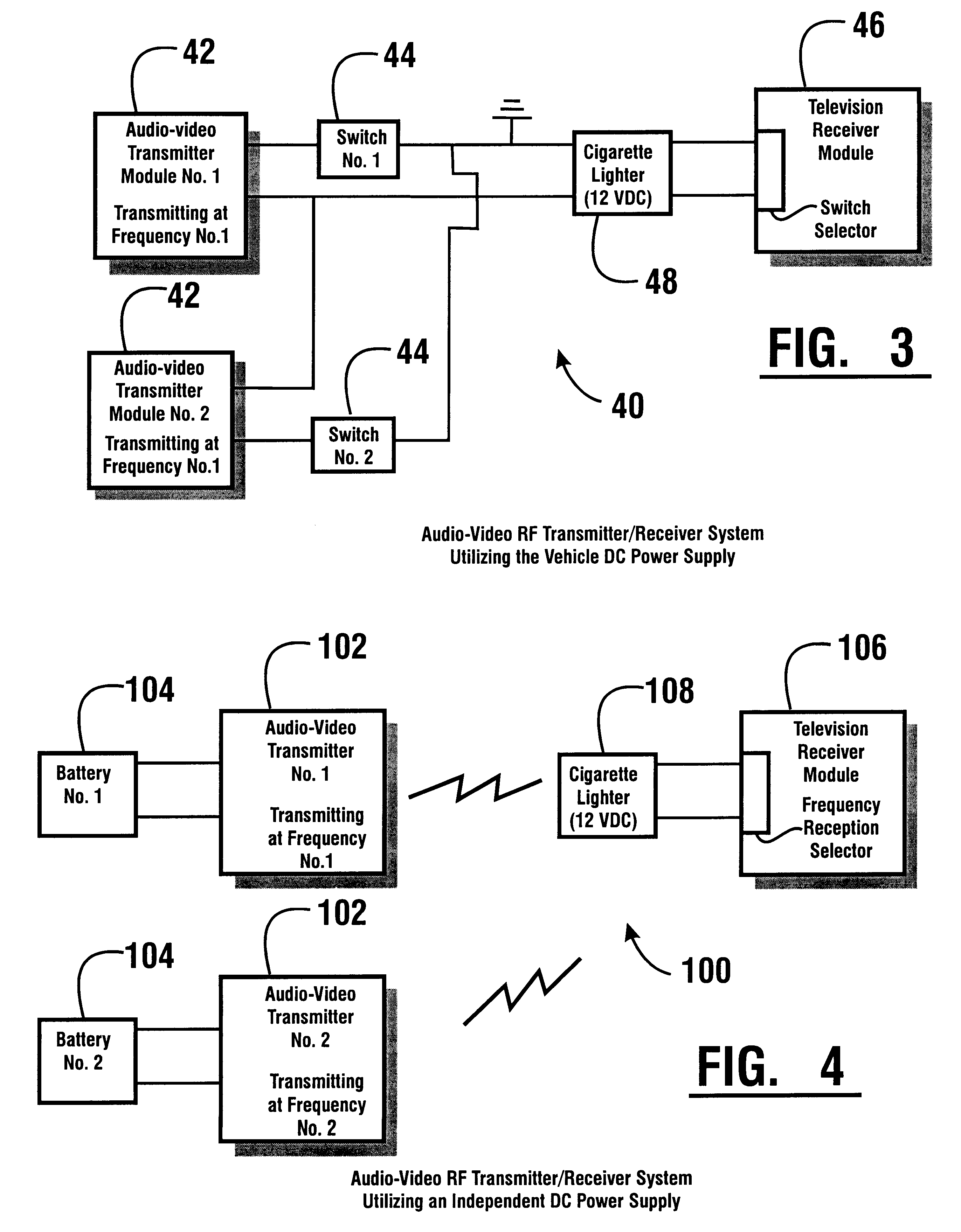
An example of the components that would make up an audio-video transmission module is shown schematically in FIG. 7. The components include a miniature video camera 200 that is connected to a radio frequency wireless transmitter 202. The transmission module also includes a microphone 204 that is similarly connected to the transmitter. The transmitter in the embodiment shown is powered on a line 206 from the DC power source of the vehicle. As shown in this embodiment, a decoder switch 208 is used for turning the transmitter on and off. Of course, the decoder switch 208 is only used in embodiments of the invention like embodiment 40 previously discussed in which the transmission modules transmit on the same frequency. In other embodiments where transmission modules transmit on different frequencies, decoder switch 208 is not required. Of course the transmitter is grounded to the vehicle as shown to enable the transmitter to both obtain power and to avoid interference and inconsistent ...

first embodiment

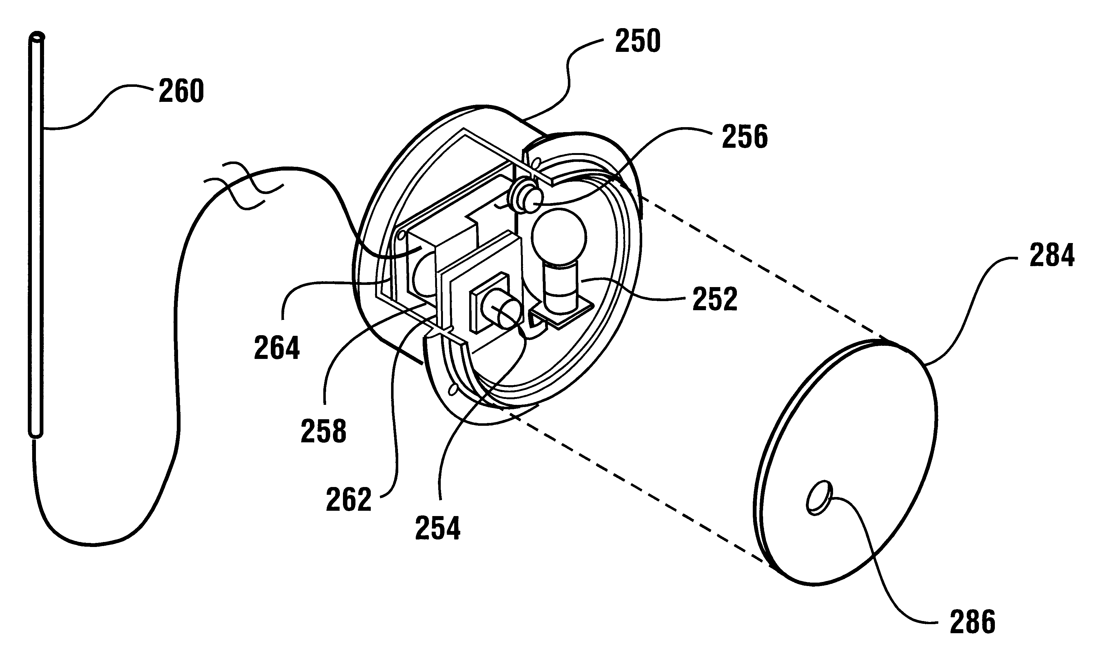
a transmission module enclosed within a tail light housing generally designated 250 is generally shown in FIG. 8. The tail light housing encloses a two-filament bulb 252 of the conventional 12-volt type. As previously discussed, the system for powering bulb 252 may involve switching within the vehicle to ground the line to the bulb to turn it on, or alternatively, to deliver power thereto. The transmission module may be supplied continuous power from the vehicle electrical system or it may have re-chargeable battery power when electrical power from the vehicle electrical system is not continuously provided. The audio-video transmission module includes a miniature video camera 254 of the type previously described as well as a microphone 256. The camera and microphone are electrically connected to a transmitter 258 that transmits a radio signal through an external antenna 260.

Electronic components are mounted in the housing to minimize the potential damage due to shock and vibration. ...

second embodiment

the invention shown in conjunction with a recreational vehicle type tail light generally indicated 300 is shown in FIG. 9. The transmission module is incorporated with the tail light components including a back up light bulb 302 and a tail and brake light bulb 304. The bulbs and the components of the transmission module are mounted on a base 306.

A miniature camera module 308 is supported on a shock resistant mount 310 in a manner similar to that previously described. A microphone 312 is also supported on the base. The microphone and camera are connected to a transmitter 314. The transmitter is connected to an unshaped antenna 316 which is configured to be fully within the housing. An advantage of having the antenna within the housing is that it is less conspicuous and also more tamper resistant.

The housing further includes environmental control features including a heating unit or heating / cooling unit generally indicated 318. The heater or heater cooler works in the manner previousl...


PUM


Abstract

A video-audio surveillance system for a motor vehicle is suitable for observing blind spots as well as for providing security for the vehicle and its contents. The system includes audio-video transmission modules positioned at selected locations on the exterior and interior of the vehicle. An operator or observer either in the vehicle or otherwise monitors the video and audio signals from the modules through a monitoring unit.

Description

This invention relates to motor vehicles. Specifically this invention relates to a system that enables an operator of a motor vehicle, such as a tractor trailer, recreational vehicle, trailer, bus, van, farm or construction equipment to view and hear sounds in the area surrounding the vehicle as well as in areas of the vehicle located remotely from the operator.Motor vehicles, particularly large vehicles such as trucks, recreational vehicles, buses, etc. have certain areas known as "blind spots." These blind spots are areas where it is difficult or impossible for an operator sitting in the driver seat of the vehicle to observe. Blind spots may exist on the sides or at the rear of a large vehicle. Other blind spots are often in areas at the front or rear of the vehicle as well as underneath the vehicle. It is important that a driver be able to view the blind spots to prevent accidents when the vehicle is in motion. In addition, it is important for the driver to view such blind spots ...

Claims


Application Information

Patent Timeline
IPC IPC(8): H04N7/18B60Q1/00
CPCH04N7/18B60Q1/0023
Inventor RAMACHANDRAN, NATARAJANLAIER, PHILIPANTRAM, HOWARD E.JUNKINS, ANDREWSRINIVASAN, ARVINDSCHUSTER, RAYMOND J.
Owner H V TECH
Learn More