Milling and pulverising apparatus and method

a pulverising apparatus and pulverising technology, applied in the field of pulverising apparatus, can solve the problems of large quantities of sample to be sampled, disadvantages of operators, and ring mills can only process small amounts of sample, and achieve the effects of increasing the efficiency of pulverizing apparatus, reducing the capacity of pulverising bowl, and greatly increasing the surface area of pulverising

Inactive Publication Date: 2001-06-19
CBS ENG
View PDF12 Cites 0 Cited by
  • Summary
  • Abstract
  • Description
  • Claims
  • Application Information

AI Technical Summary

Benefits of technology

Using two or more pulverising discs considerably increases the efficiency of the pulversing apparatus compared with existing pulverising devices. The pulverising surface area is greatly increased, with pulverising occurring between the surfaces of the pulverising discus and the pulverising bowl, as well as between the surfaces of two or more adjacent pulverising discs.
The variable capacity of the pulverising apparatus also allows a variable size sample to be added to the pulverising bowl. The capacity of the pulverising bowl may be varied depending on the size of the sample inserted, with the volume reduced to allow easy contact between the pulverising discs and the lid of the pulverising bowl.
Increasing the frequency of the driving apparatus also increases the speed of operation of the device. Small sized particle mixes of a highly homogeneous nature are provided by the pulverising apparatus in a much shorter time period than would normally be possible with existing pulverising technology.
The use of multiple pulverising discs allows an operator to easily remove the mill discs without need of a mechanical lifting device. This decreases the expense of the invention, with the entire weight of a large pulverising discus broken down into several components which may be lifted out of the mill one by one by an operator.
The use of a convex top surface on a pulverising discus allows material located on the top of the discus to roll off the surface and back into the middle and centre of the pulverising bowl. This feature promotes ready recirculation of sample material during operation.
The present invention may operate effectively after continued use where the discs have worn the base of the pulverising bowl into a curve. This is of great advantage compared to existing milling and pulverising devices where bases of these mills worn into curves must be replaced if the mill is to operate effectively. This creates a large cost and time saving to the operator of the present invention.

Problems solved by technology

Some analyses also require large quantities of the sample to be sampled.
In the case of analysing the chemical components of ore in the form of rocks, the preparation of the sample proposes several problems.
This mill design is effective but has a major problem which disadvantages the operator.
A ring mill can only process small amounts of sample in one processing operation.
If too much sample is added to the bowl it ends up choking up the puck and rings, limiting the movement of the rings when the device is driven.
This causes a severe problem, as pulverisation of enough sample for an analysis turns into a long and tedious job, with several processing stages being required.
If the materials are too large or coarse the ring mill can not effectively pulverise the sample, or will require an extremely long pulverising period within which to process a sample to their required particle size and homogeneity.
The discus mill solves some of the disadvantages involved with using a ring mill because it can process a large amount of sample.
However, the discus mill still relies on long processing times to pulverise a sample down to the required sized particles.
This results in slow sample preparation.
An operator is again limited in the amount of sample they can process in a particular period of time.
An additional problem associated with discus mills is removal of the sample once pulverisation has occurred.
The discs employed in a conventional discus mill can weigh in excess of 25 kilos, which operators find difficult to lift and move easily.
This results in increased expense, as more equipment is required for sample preparation, and also slows down sample preparation, the operator has to control and manoeuvre a secondary piece of mechanical apparatus to allow the sample to be removed from the Mill.
The performance of the discus will fall steadily with use as its weight decreases, until it must be replaced because pulverising times are too long.
The bowl is an expensive component, and because in single discus mills a curved bowl base is used, the bowl cannot easily be refurbished with a replacement base plate.
As can be appreciated by one skilled in the art ball mills do not operate as efficiently as other milling and pulverising devices.
This make ball mills relatively inefficient when compared to other forms of milling apparatus.
Some laboratories process thousands of samples a day and therefore any reduction in pulverising time is a considerable cost and labour saving.

Method used


Image

  • Milling and pulverising apparatus and method
  • Milling and pulverising apparatus and method

Examples


Embodiment Construction

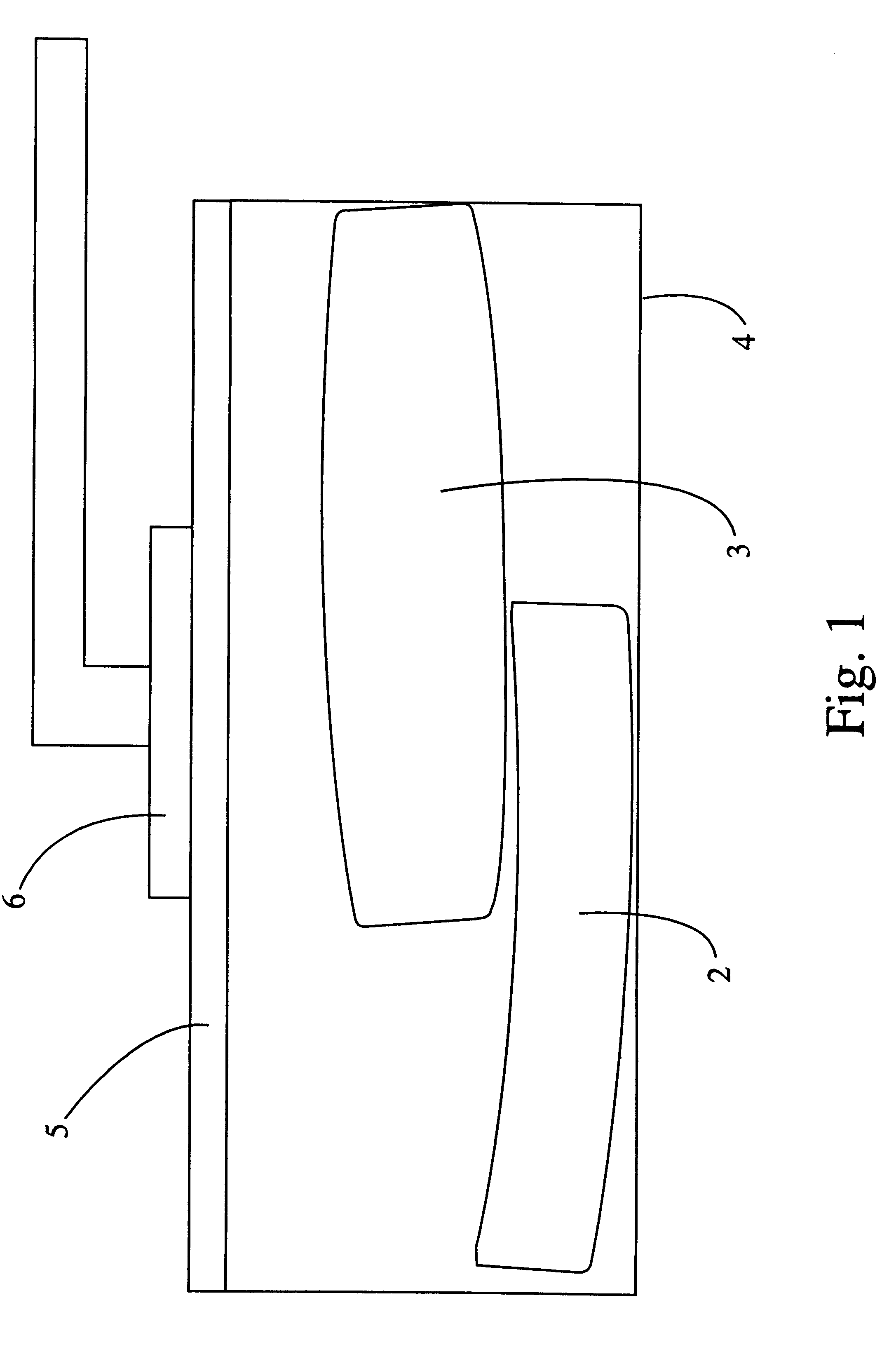
FIG. 1 illustrates a schematic view of the pulverising apparatus 1.

Pulverising apparatus 1 includes pulverising weights, in this embodiment pulverising discus 2 and pulverising discus 3.

Pulverising discus 3 is positioned on top of pulverising discus 2, with both discs being oriented substantially horizontally with respect to the pulverising apparatus 1.

Pulverising discs 2 and 3 are configured so that the adjacent sides of each discus are matching surfaces. As shown in FIG. 1 and FIG. 2 pulverising discus 2 has an upper concave curved surface, while pulverising discus 3 has a lower convex curved surface, which fits easily into the top surface of pulverising discus 2.

The upper surface of pulverising discus 3 is shaped as a convex curve. This allows any material present of the top surface of pulverising discus 3 to roll off the top of the pulverising discus back down into the centre and bottom of the pulverising bowl 4.

Both pulverising discs 2 and 3 are located within the pulverising r...


PUM


Abstract

The specification describes a method and associated apparatus for pulverising materials, wherein the pulverising apparatus includes a receptacle, two or more pulverising weights and a driving mechanism linked to the receptacle wherein the pulverising weights are disposed substantially horizontally with respect to the receptacle.The method of operating the apparatus includes the steps of:a) placing the pulverising weights in the receptacle, wherein the pulverising weights are disposed substantially horizontally with respect to the receptacle, andb) activating the driving mechanism, causing material(s) retained in the receptacle to be ground by the pulverising weights.

Description

This invention relates to apparatus used to mill or pulverise materials, especially ore.Reference throughout this specification will now be made to the material as being ore in the form of rocks.It should be appreciated that other materials can be used with the present invention. These materials may for example include sand, coal, wood, slag, clay or sinter.A number of chemical analyses require the sample to be tested in a fine homogeneous powdered form. This is the case with some tests performed on ore samples, which require the sample to be pulverised into particles of diameters smaller than 75 microns.Some analyses also require large quantities of the sample to be sampled. The analysis in question may consume a large amount of the sample, or several analyses may be required to ensure the results obtained are repeatable.In the case of analysing the chemical components of ore in the form of rocks, the preparation of the sample proposes several problems. Large quantities of rock nee...

Claims


Application Information

Patent Timeline
Patent Type & Authority Patents(United States)
IPC IPC(8): B02C17/00B02C17/10
CPCB02C17/10
Inventor DEVEREUX, IAN
Owner CBS ENG
Why Eureka
Try Eureka