Video signal converting apparatus with display mode conversion and a display device having the same
- Summary
- Abstract
- Description
- Claims
- Application Information
AI Technical Summary
Benefits of technology
Problems solved by technology
Method used
Image
Examples
Embodiment Construction
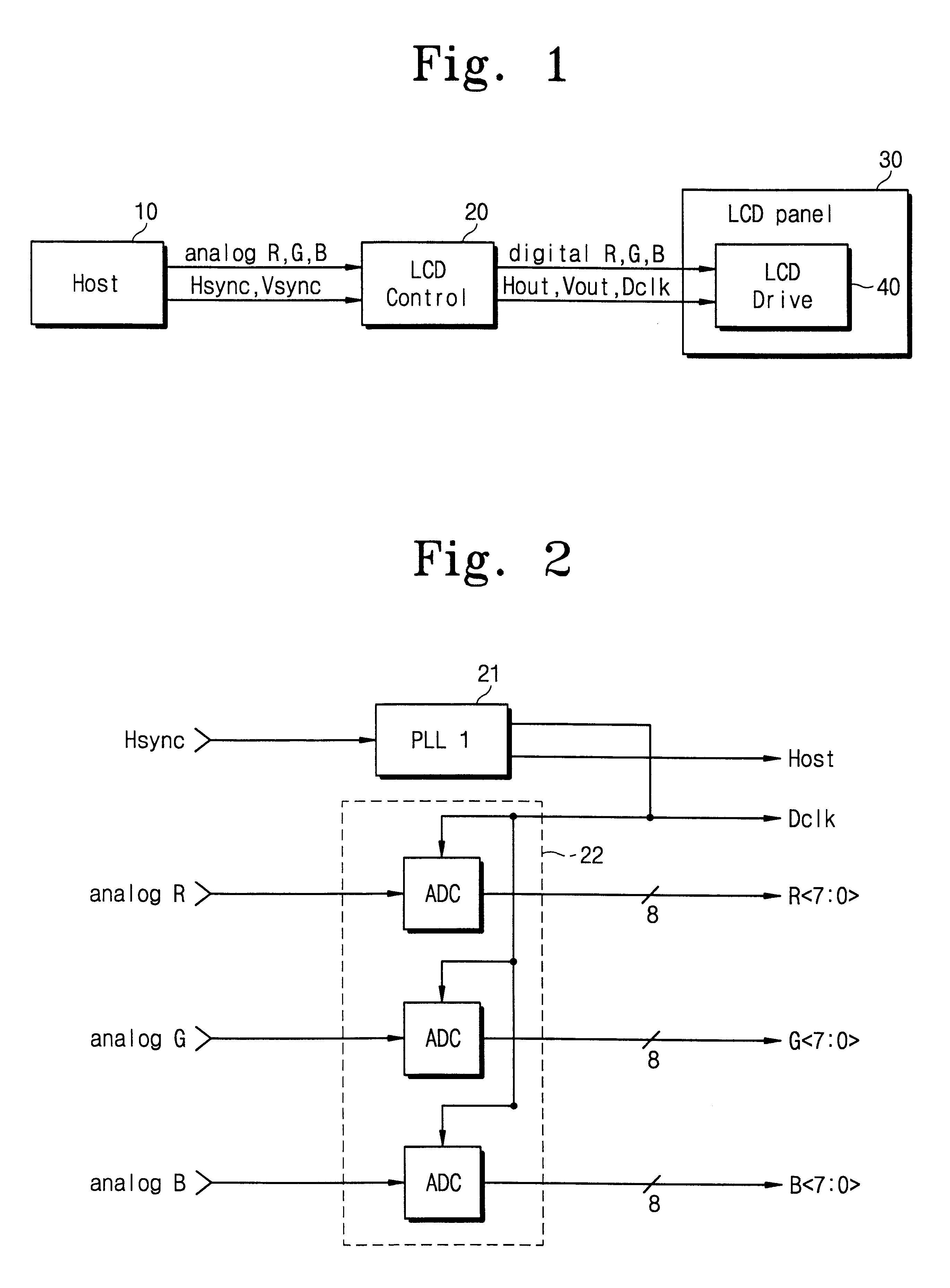
FIG. 1 is a schematic block diagram showing the construction of an active matrix LCD device as discussed in the Background of the Invention above. A host 10 is connected to an LCD control unit 20 which is in turn connected to an LCD driving circuit 40 of an LCD panel 30.
FIG. 2 is a block diagram showing the construction of an earlier LCD control unit as also previously discussed in the Background of the Invention above.
The LCD control unit 20, which is provided to control the LCD panel 30, has a PLL circuit 21 and an ADC 22. The PLL circuit 22, as is well known in the art, has a phase sensor, a voltage controlled oscillator, a divider, and an output generator.
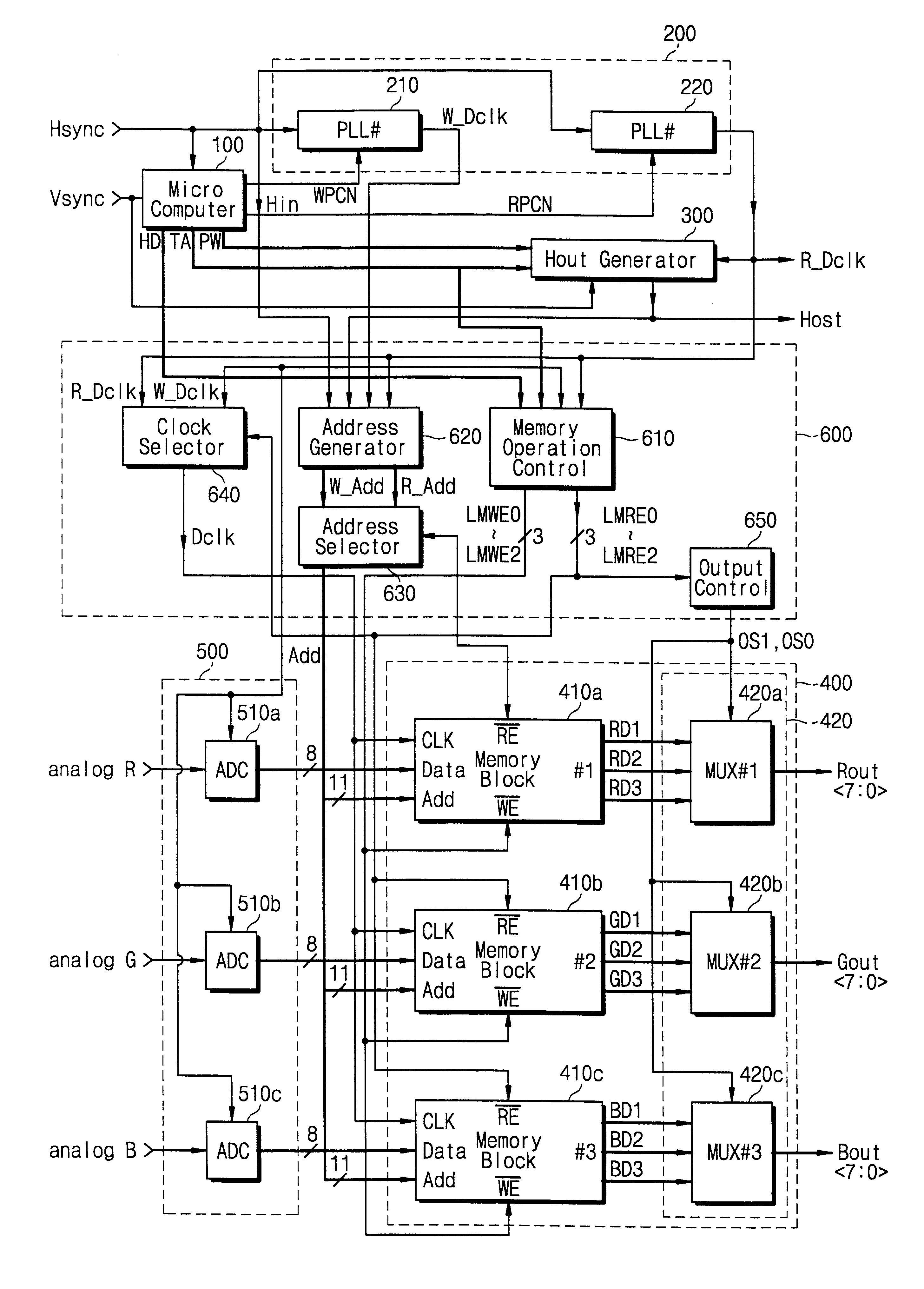
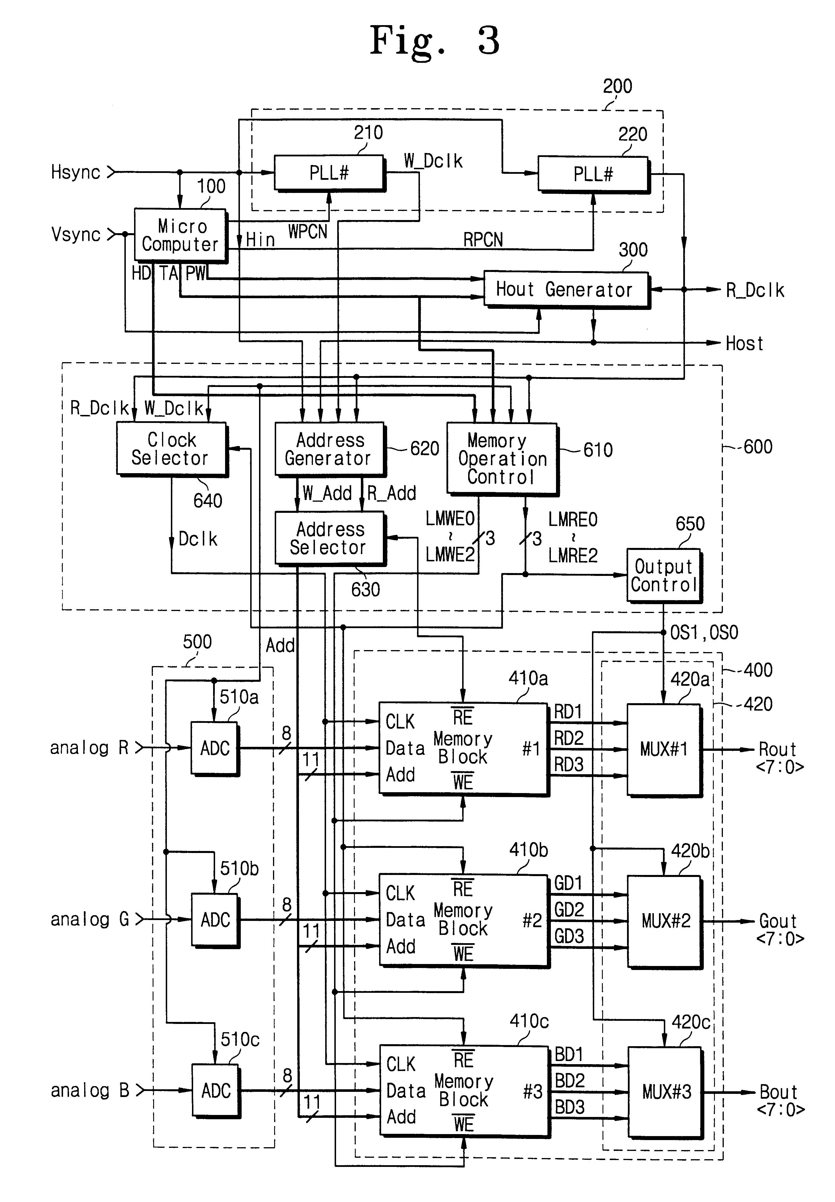
It is assumed that a novel video signal converting apparatus according to the present invention is connected to an XGA mode supporting LCD panel and VGA mode video signals are fed from a host to the apparatus. The video signal apparatus then functions as an LCD controller. With the apparatus, the frequency of the vertical synch...
PUM
| Property | Measurement | Unit |
|---|---|---|
| frequencies | aaaaa | aaaaa |
| width | aaaaa | aaaaa |
| brightness | aaaaa | aaaaa |
Abstract
Description
Claims
Application Information
 - R&D
- Intellectual Property
- Life Sciences
- Materials
- Tech Scout
- Unparalleled Data Quality
- Higher Quality Content
- 60% Fewer Hallucinations
Browse by: Latest US Patents, China's latest patents, Technical Efficacy Thesaurus, Application Domain, Technology Topic, Popular Technical Reports.
© 2025 PatSnap. All rights reserved.Legal|Privacy policy|Modern Slavery Act Transparency Statement|Sitemap|About US| Contact US: help@patsnap.com


