
Gas operated apparatus and method for maintaining relatively uniformed fluid pressure within an expandable well tool subjected to thermal variants

a technology of fluid pressure and expandable wells, applied in the field of subterranean wells, can solve problems such as project failure, adverse effect, and jeopardizing the integrity of sealing and even anchoring devices

Inactive Publication Date: 2001-04-10
WEATHERFORD TECH HLDG LLC
View PDF18 Cites 29 Cited by
  • Summary
  • Abstract
  • Description
  • Claims
  • Application Information

AI Technical Summary

Benefits of technology

With regard to physical characteristics of the apparatus, the volumetric size of the first chamber at the end of the setting operation is determined by the expansion ratio for that tool in each specific service job. Almost all projects that use thru-tubing inflatable devices have an expansion ratio less than 3.25:1. Many projects performed in the world-wide industry have expansion ratios less than 3:1, and most of them have expansion ratios less than 2.5:1. The volumetric size of the second chamber in an actual tool can be designed to satisfy service conditions for a 3.25:1 expansion ratio and a 200.degree. F. thermal cycle range. The tool and method of the present invention can provide quasi-static pressure maintenance over a thermal cycle range greater than 200.degree. F. for all applications where the expansion ratio is less than 3.25:1. This versatility benefits users because they only need to inventory and maintain one size of the invention in order to satisfy all service jobs for each size of inflatable tool.

Problems solved by technology

Frequently, the seal is established subsequent to the setting of such device in the well and will be adversely effected by temperature variances of the device or in the vicinity of the device.
Such temperature variances can cause expansion or contraction of the sealing mechanism, thus jeopardizing the sealing and even anchoring integrity of the device over time.
In more dramatic situations, anchoring of the device in the well bore can be lost and the differential pressures across the device can cause "corkscrewing" of the coiled tubing or work string, resulting in project failure, expensive solution of the corkscrew problem and substantial operational risks.
On the other hand, the same inflatable tool is also adversely affected by an increase in device temperature during certain types of secondary and tertiary injection techniques utilizing, for example, the injection of steam.
Some prior art devices containing inflatable packer components have been known to have the inflatable bladder element actually rupture, due to exposure to increased pressure within the bladder and interconnected chambers and passageways as steam flows through the device and is injected into the well zone.

Method used


Image

  • Gas operated apparatus and method for maintaining relatively uniformed fluid pressure within an expandable well tool subjected to thermal variants
  • Gas operated apparatus and method for maintaining relatively uniformed fluid pressure within an expandable well tool subjected to thermal variants
  • Gas operated apparatus and method for maintaining relatively uniformed fluid pressure within an expandable well tool subjected to thermal variants

Examples


Embodiment Construction

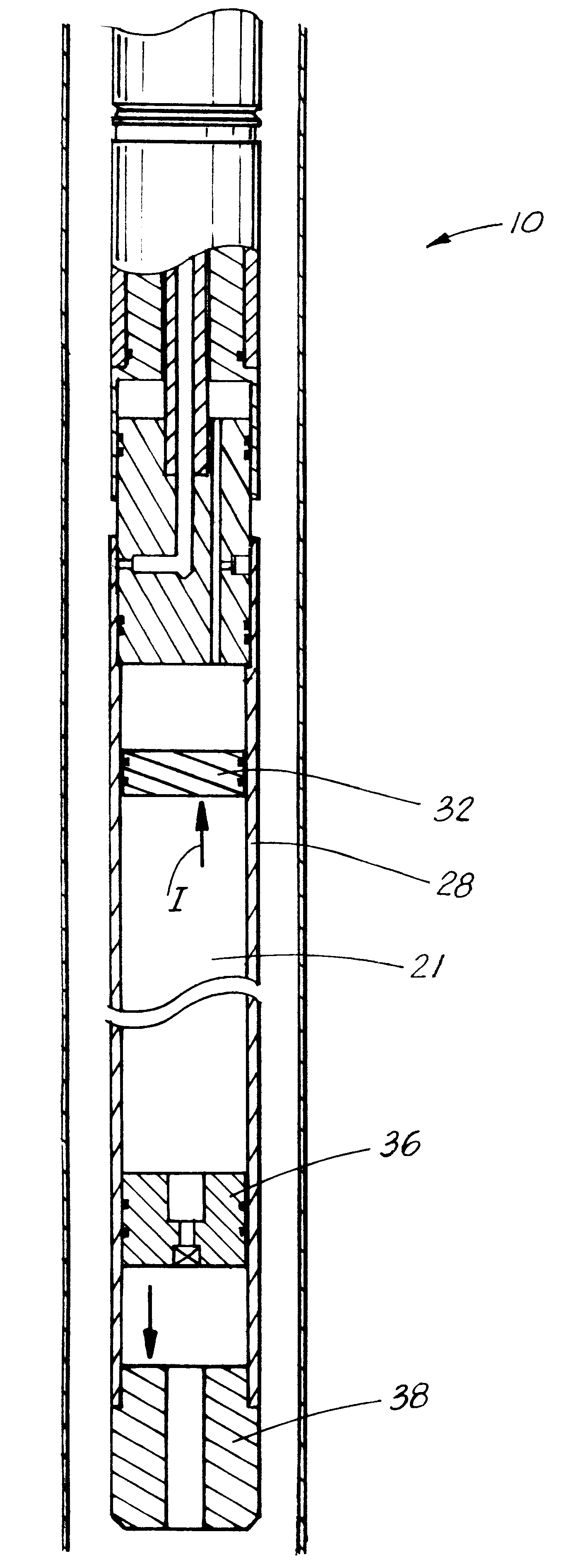
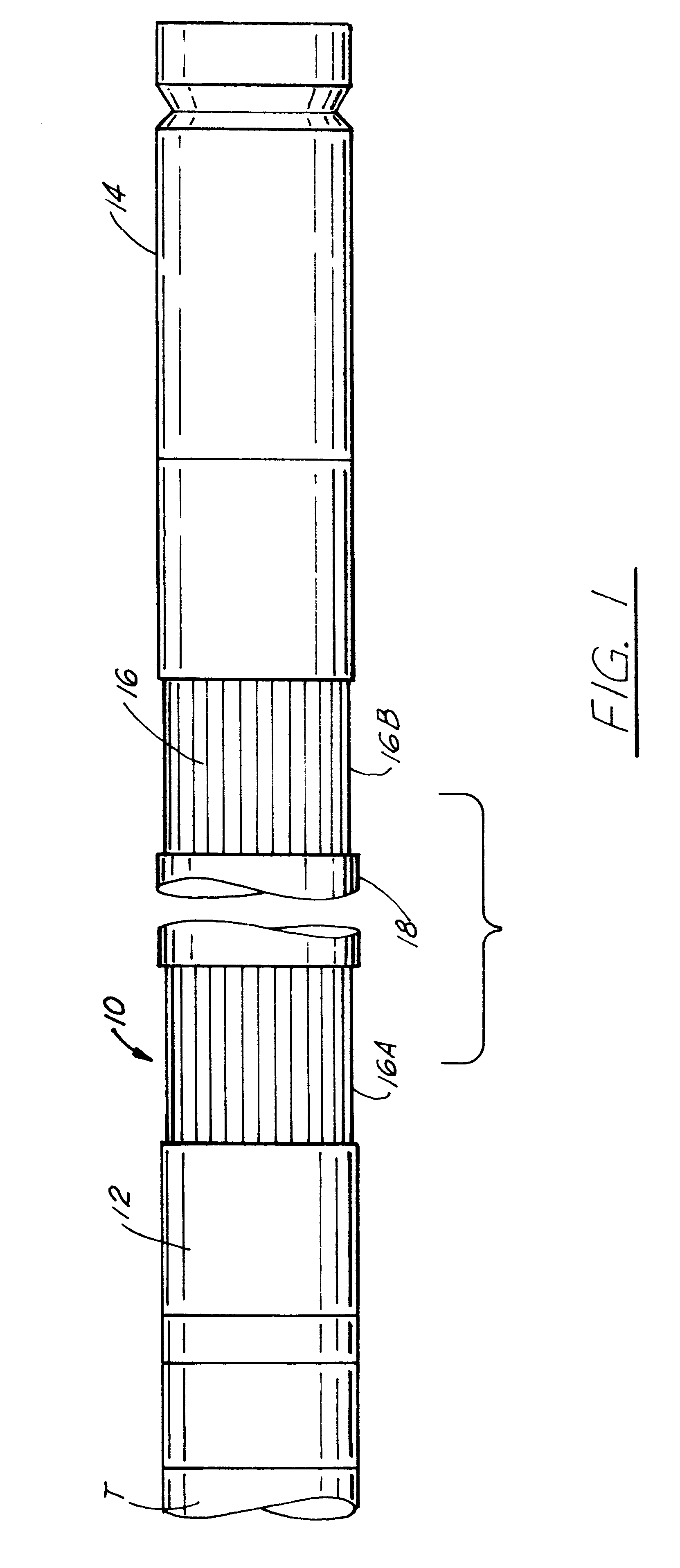
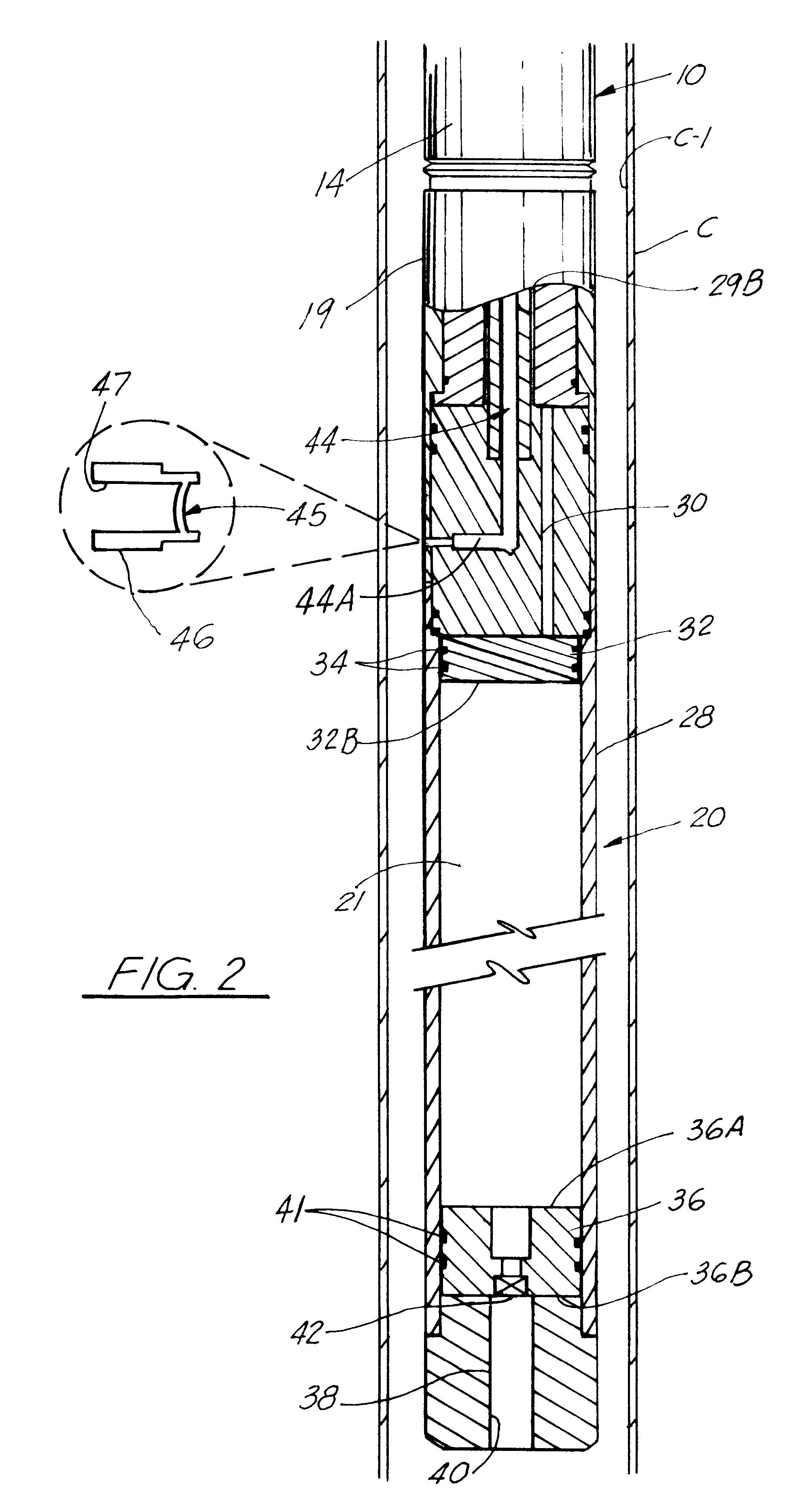
Referring first to FIG. 1, a down hole tool such as an inflatable packer 10 is shown, in which the invention can be used. The invention can also be used in many other types of down hole tools which utilize inflatable elements of the type described. The packer 10 includes upper and lower collars 12, 14, respectively. The packer 10 is connected in conventional fashion, such as by threads, connector, or otherwise, through the upper collar 12 to a carrier T extending to the top of the well. The carrier T may be a tubular conduit, such as coiled tubing, a section of work string, electric line, or the like.

The packer 10 includes a series of metallic ribs or slats 16 which overlap and extend longitudinally between the collars 12, 14, in conventional fashion. A conventional bladder (not shown) formed of an elastomeric material is provided beneath the ribs 16, which can be expanded through the introduction of pressurized fluid from any number of sources in a well known way.

The tool 10 includ...


PUM


Abstract

A thermal compensating apparatus method for maintaining a substantially constant fluid pressure within a subterranean well tool of the type that includes a bladder that is selectively expandable upon the introduction of pressurized actuation fluid for actuating said tool at a location in a well. A body includes first and second fluid chambers. The first fluid chamber houses a substantially incompressible fluid and communicates with the actuating fluid used for activating said tool in the well. The second fluid chamber is charged with a compressible fluid. Both chambers define first volumetric sizes within the body upon actuation of said tool in the well. The fluid chambers are operatively connected to each other without transmitting fluid there between so that changes in the volumetric size of the first chamber caused by temperature variations in the actuation fluid will change the volumetric size of the second fluid chamber for maintaining the actuating fluid at a substantially constant pressure.

Description

1. Field of the InventionThe invention relates generally to subterranean well tools such as inflatable packers, bridge plugs or the like, which are set through the introduction of fluid into an expandable elastomeric bladder and, more particularly, to a gas operated apparatus and method for maintaining a relatively uniform fluid pressure in the bladder when the tool is subjected to thermal variants after setting.2. Description of ProblemsIt is known among those skilled in the use of these types of inflatable devices that they are subject to changes in inflation pressure when the temperature of the inflation fluid varies from its initial inflation temperature. Typically, an increase in fluid temperature results in increased inflation pressures, and a decrease results in decreased inflation pressures. An increase in inflation pressure can make the tool susceptible to burst failure. A decrease in inflation pressure can diminish anchoring between the tool and the well bore to a point wh...

Claims


Application Information

Patent Timeline
IPC IPC(8): E21B33/127E21B33/12
CPCE21B33/127
Inventor WILSON, PAUL J.CARISELLA, JAMES V.
Owner WEATHERFORD TECH HLDG LLC
Learn More