
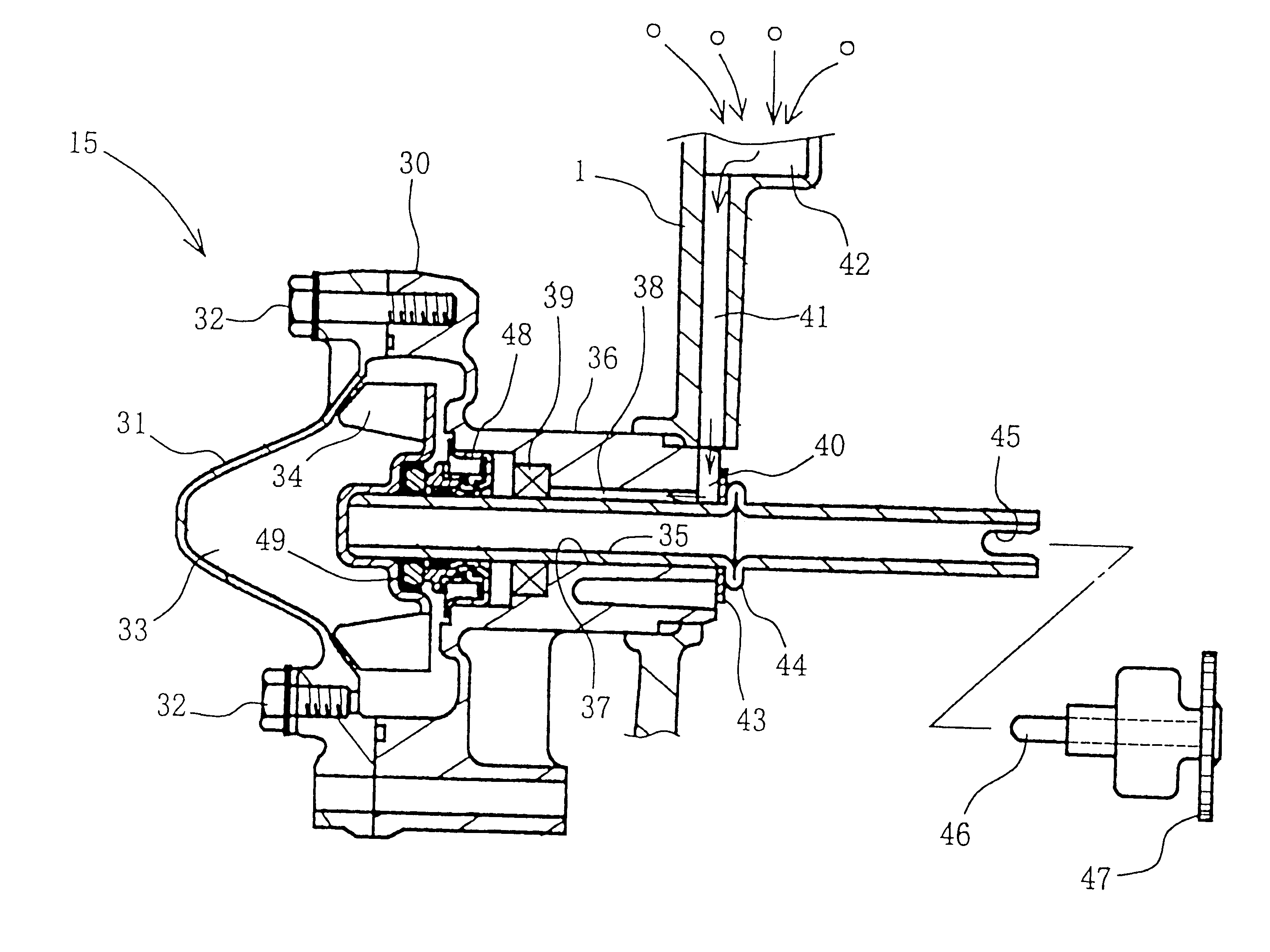
Engine water pump structure

Inactive Publication Date: 2001-04-10
HONDA MOTOR CO LTD
View PDF1 Cites 14 Cited by
  • Summary
  • Abstract
  • Description
  • Claims
  • Application Information

AI Technical Summary

Problems solved by technology

Further, the manufacturing and repair process is difficult.

Method used


Image

  • Engine water pump structure
  • Engine water pump structure
  • Engine water pump structure

Examples


Embodiment Construction

An engine structure will be outlined with reference to FIG. 2. The engine is a water-cooled four-cycle DOHC (double overhead camshaft) engine. The engine includes a crankcase 1, a cylinder 2, a cylinder head 3, and a cylinder head cover 4 which is a part of the cylinder head 3. A piston 5 is slidably housed in the cylinder 2 and is coupled to a crankshaft 6 (the center thereof is shown in FIG. 2) in the crankcase 1. A combustion chamber is provided between the piston 5, cylinder 2 and cylinder head 3.

An inlet port 7 and an exhaust port 8 are provided on the cylinder head 3 and communicate with the combustion chamber. The inlet port 7 and exhaust port 8 are opened and closed by an inlet valve 10 and an exhaust valve 11, respectively. The inlet valve 10 end exhaust valve 11 are driven by cams on camshafts 12 and 13, which are rotated in synchronization with the crankshaft 6.

A water jacket 14 is provided on the cylinder 2 and the cylinder head 3, and receives cooling water from a water...


PUM


Abstract

A water pump includes a pump body and a pump cover. An impeller is housed in a pump chamber defined by the pump body and pump cover. The impeller is attached to one end of a hollow pump shaft. The pump shaft is engaged with a driving section at its other end. An intermediate part of the pump shaft is supported by a shaft support section, in the form of a cylindrical section, of the pump body. The shaft support section is longer than a diameter of the pump shaft. The shaft support section is lubricated via an oil groove. One end of the shaft support section is brought into contact with a flange of the pump shaft via a washer. The flange is integrally formed on the pump shaft by a beading process.

Description

1. Field of the InventionThe present invention relates to a water pump for a water-cooled engine.2. Description of Related ArtJapanese Utility Model Publication No. Hei 6-31197 discloses a structure of a water pump for a water-cooled engine of a motorcycle. In the water pump, an impeller is attached to one end of a hollow pump shaft, and a pump gear is attached to the other end of the pump shaft. The pump gear rotates in response to rotation of a crankshaft. The pump shaft is supported by a crankcase of the crankshaft.The pump gear receives a thrust load from a pin. The pin has its opposite ends supported in the crankcase via the pump gear and is orthogonal to the crankcase. The pump gear is surface-supported by the crankcase.In order to receive the thrust load by the pin, as described above, a drilling process and a force-fitting process are required in order to install the pin. Therefore, the number of components, including the pin itself, is increased. Further, the manufacturing ...

Claims


Application Information

Patent Timeline
IPC IPC(8): F04D29/04F01M9/00F01M9/10F01P5/00F01P5/10F01M9/08F01M11/02F01P5/12F04D29/041F04D29/043
CPCF01M9/108F01P5/10F04D29/0413F04D29/043F01M9/08F01M11/02F02B2275/18F05B2240/61
Inventor NAKANO, SHINICHITAKAHASHI, KATSUNORIOKA, TOMOOSUZUKI, YOSHIKIKOBAYASHI, CHUTARO
Owner HONDA MOTOR CO LTD
Learn More