
Stereoscopic computer graphics moving image generating apparatus

a technology of moving image and computer graphics, applied in the field of three-dimensional cg (computer graphics) moving image generation apparatus, can solve the problems of fatigue and eyestrain, restricting the visual system of the viewer, and requiring a limited relative velocity

Inactive Publication Date: 2001-03-20
PANASONIC CORP
View PDF11 Cites 46 Cited by
  • Summary
  • Abstract
  • Description
  • Claims
  • Application Information

AI Technical Summary

Problems solved by technology

However, with the above prior art stereoscopic CG image generating apparatus, the motion parameters of the plurality of cameras and the motion parameters of the subject, if not properly adjusted, may often not match the visual functions of the viewer, straining the visual system of the viewer.
Furthermore, to provide proper depth perception by motion parallax (relating to the relative velocity between a plurality of target objects), the relative velocity also must be limited.
Accordingly, the prior art has had the problem that unless these parameters are always set correctly, improper images are generated that can cause unnaturalness and can lead to fatigue and eyestrain.

Method used


Image

  • Stereoscopic computer graphics moving image generating apparatus
  • Stereoscopic computer graphics moving image generating apparatus
  • Stereoscopic computer graphics moving image generating apparatus

Examples


Embodiment Construction

The present invention will be described below with reference to the drawings illustrating the preferred embodiments thereof.

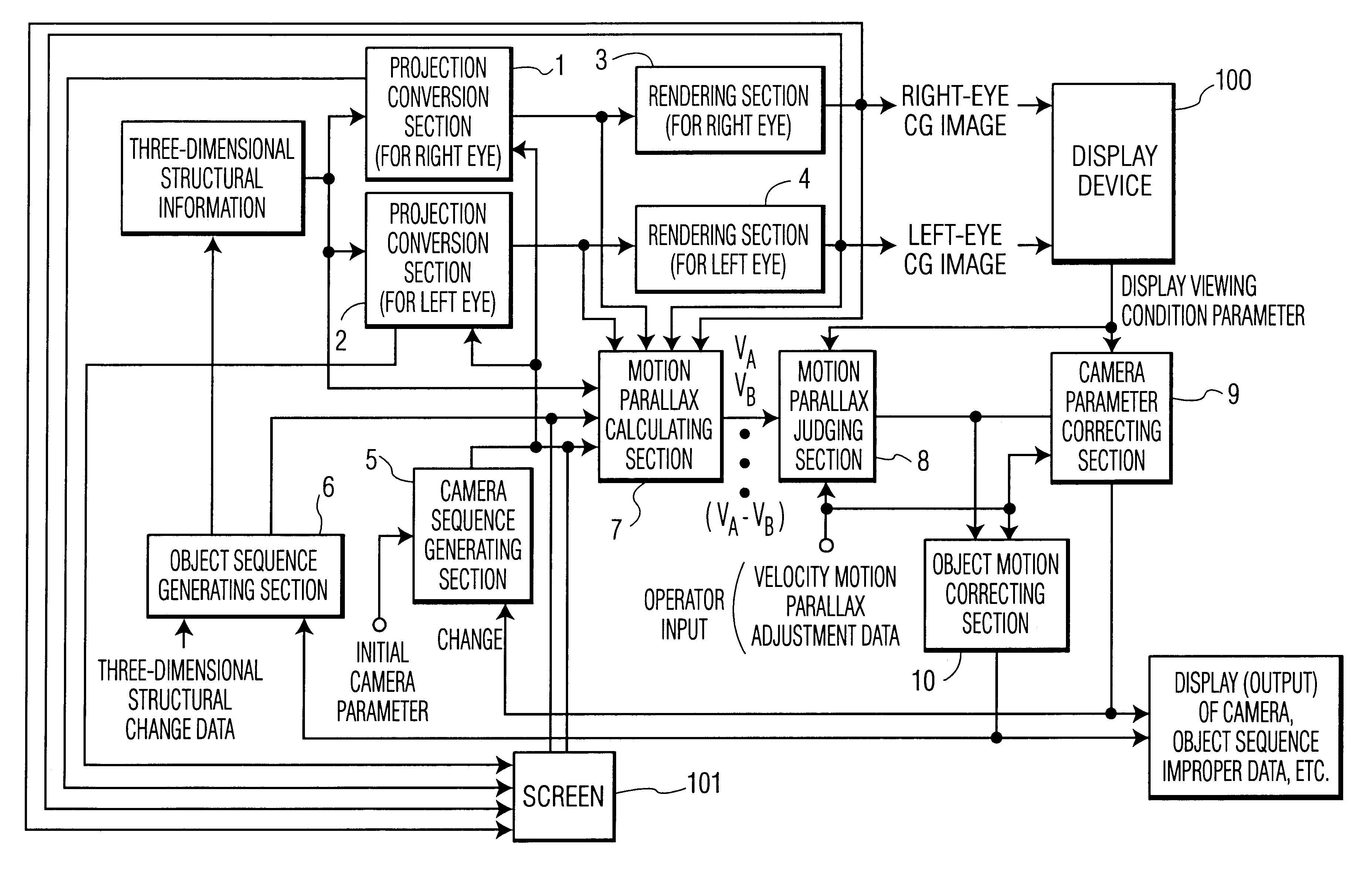
FIG. 1 is a diagram showing the configuration of a stereoscopic CG image generating apparatus according to a first embodiment of the present invention. In FIG. 1, reference numerals 1 and 2 are projection transformation sections for accepting three-dimensional structural information at their inputs and for transforming the structural information, 3 and 4 are rendering sections for rendering the outputs of the projection transformation sections 1 and 2, 5 is a camera sequence generating section, and 6 is an object sequence generating section. These elements are the same as those used in the prior art stereoscopic CG image generating apparatus.

This embodiment differs from the prior art stereoscopic CG image generating apparatus by the inclusion of a motion parallax calculating section 7, a motion parallax judging section 8, a camera parameter correcting section 9...


PUM


Abstract

A stereoscopic computer graphics (CG) moving image generating apparatus includes a projection transformation section for generating a two-dimensional projection image as viewed from a camera using three-dimensional structural information of a subject; rendering sections for calculating a viewable image from the output of the projection transformation section; a camera sequence generating section for generating camera parameters defining projection transformation in the projection transformation section and capable of generating a moving image by varying the same; a motion calculating section for calculating the motion and / or motion parallax of a displayed subject using at least one of the three-dimensional structural information, the output of the projection transformation section, the output of the rendering sections, and the output of the camera sequence generating section; and a camera parameter correcting section for automatically or manually correcting the camera parameter so that the motion and / or motion parallax of the displayed subject do not exceed a tolerance range of a viewer, based at least on the output of the motion calculating section, the size of a screen for image display, and the viewing distance of the viewer.

Description

1. Field of the InventionThe present invention relates to the generation of three-dimensional CG (computer graphics) moving images, and more particularly to a stereoscopic CG moving image generating apparatus capable of presenting the viewer with proper motion and depth perception according to the camera and subject motions, magnitude of motion parallax, and display viewing conditions.2. Description of the Prior ArtAn example of a prior art stereoscopic CG image generating apparatus is shown in FIG. 9. According to this apparatus, three-dimensional structural information, describing a three-dimensional shape of a subject by a surface model, is input (the subject is approximated by a plurality of small surfaces called polygons, the structural information defining the three-dimensional positions of the vertices of each polygon and the faces and edges formed by the polygons), and the subject defined by this information is arranged in a world coordinate system. Then, projection transfor...

Claims


Application Information

Patent Timeline
IPC IPC(8): G06T15/10H04N13/00H04N13/221H04N13/239
CPCG06T15/10H04N13/0022H04N13/0278H04N13/0296H04N13/0221H04N13/0239H04N13/0257H04N13/0289H04N2013/0081H04N2013/0085H04N2013/0096H04N13/289H04N13/221H04N13/279H04N13/257H04N13/296H04N13/239H04N13/128G06T17/00
Inventor UOMORI, KENYAMORIMURA, ATSUSHI
Owner PANASONIC CORP
Learn More