Eureka AIR delivers breakthrough ideas for toughest innovation challenges, trusted by R&D personnel around the world.

Portable illuminated warning sign

Inactive Publication Date: 2001-03-20
WHELEN ENGINEERING COMPANY
View PDF8 Cites 69 Cited by
  • Summary
  • Abstract
  • Description
  • Claims
  • Application Information

AI Technical Summary

Problems solved by technology

Maintenance of portability has previously dictated that electrically energized devices, i.e., light sources, not be used in such signs because the power requirements for such light sources would require unduly large and heavy batteries.

Method used


Image

  • Portable illuminated warning sign
  • Portable illuminated warning sign
  • Portable illuminated warning sign

Examples


Embodiment Construction

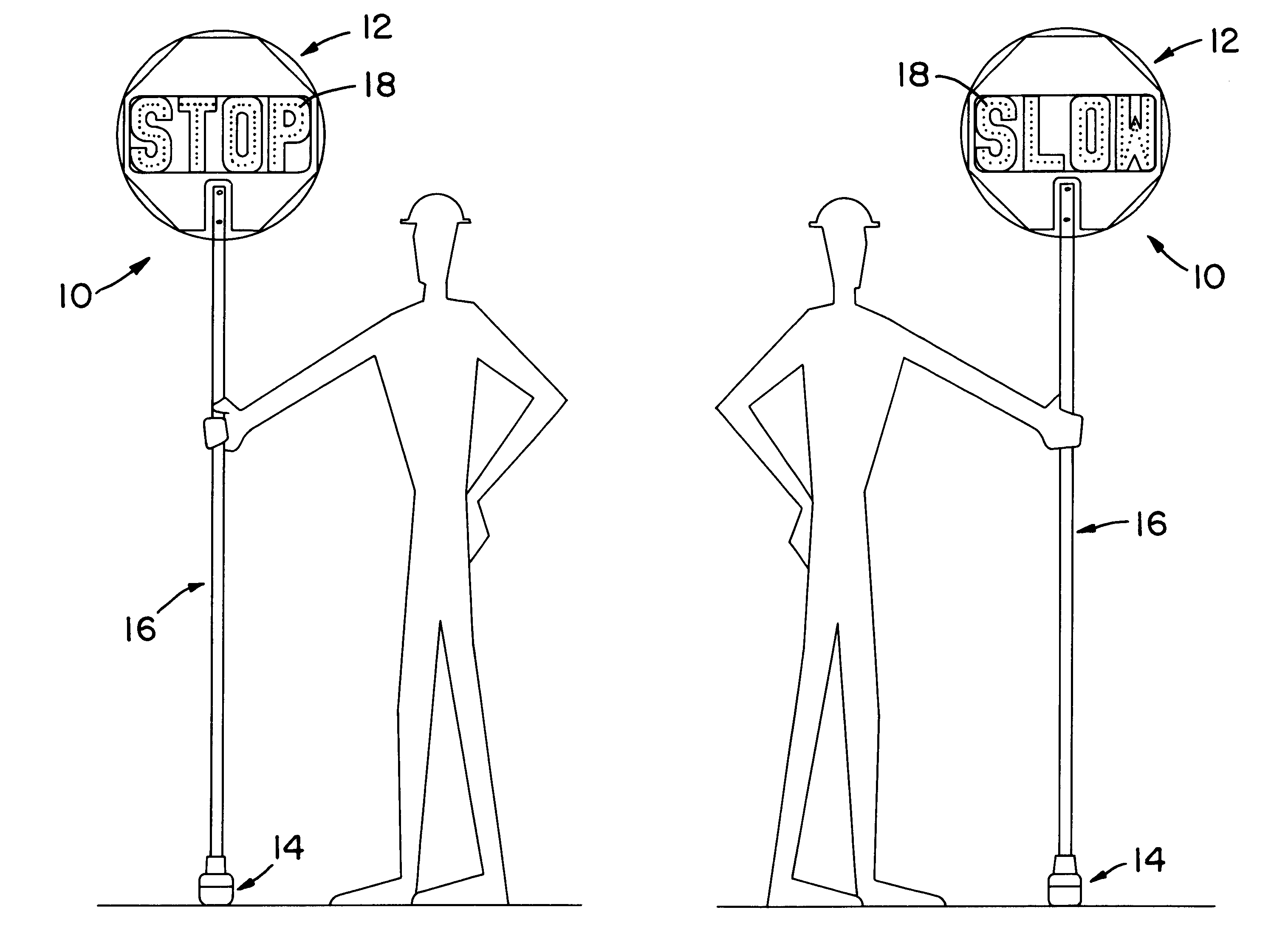
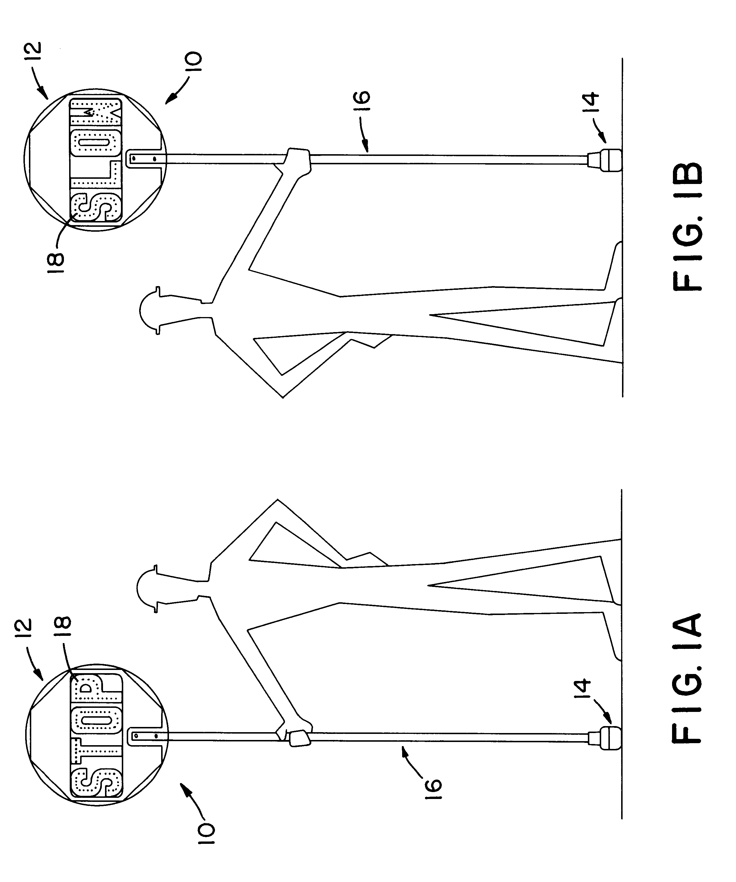
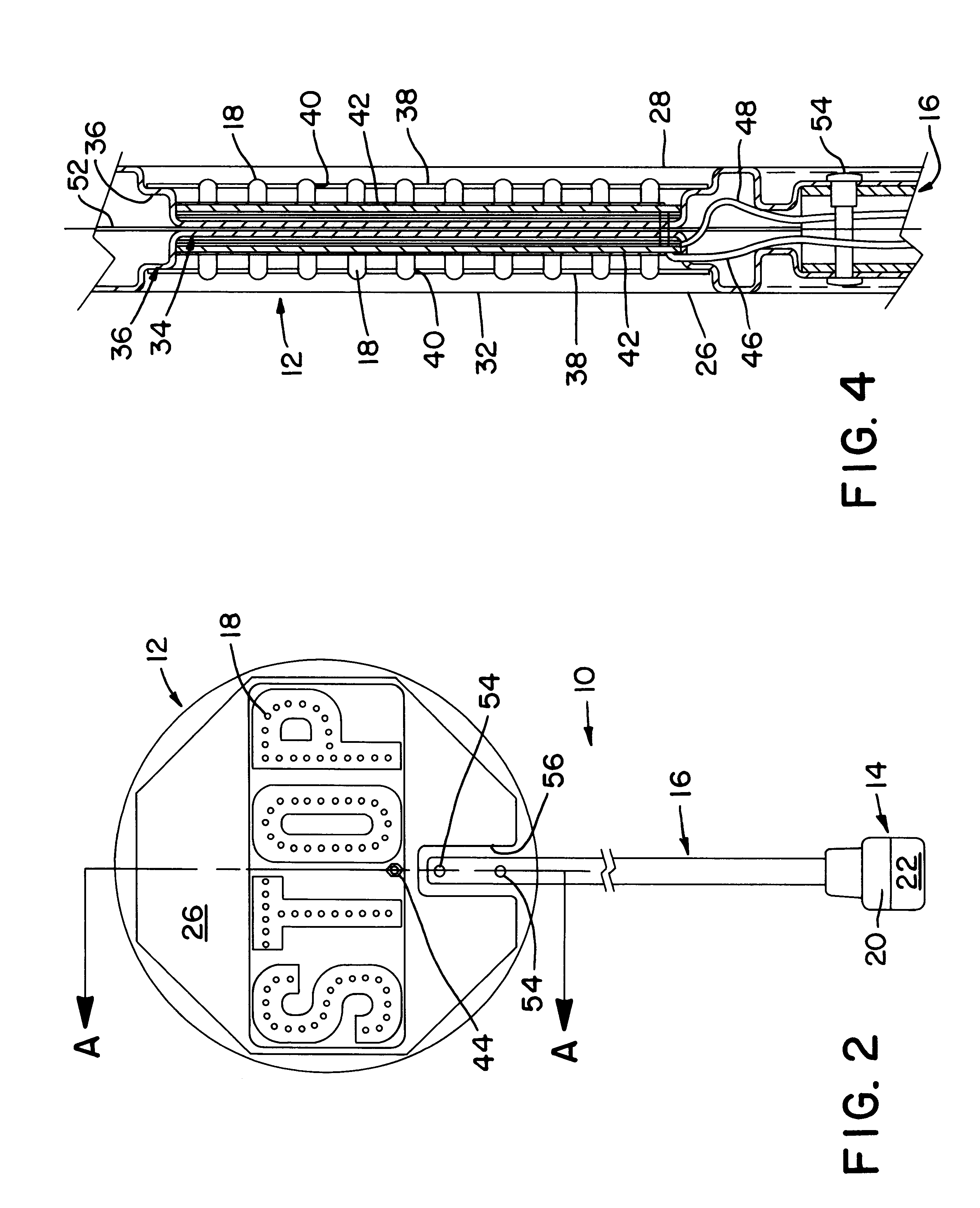
With reference now to the drawings, a warning sign in accordance with the present invention is indicated generally at 10 in FIGS. 1 and 2. The three major components of sign 10 are the message or sign board 12, a two piece base 14 and the pole 16 which interconnects the board and base. As may be seen by comparison of FIGS. 1A and 1B, board portion 12 of sign 10 bears a different printed informational message, i.e., an instruction word, on each side. Each of the letters comprising these words is further outlined by a linear array of light emitting diodes 18. In one reduction to practice of the invention, the LED's 18 comprised 5 mm A1InGaP devices which, when energized, generate 2000 millicandella. The LED arrays, as clearly shown, are positioned within the bounds of the printed letters. Thus, when energized, the LED's will increase the distance from which the information to be conveyed may be read and will reinforce the message, i.e., STOP or SLOW in the disclosed example. The board...


PUM


Abstract

LED arrays which reinforce the printed message are incorporated in hand held warning signs. Power for the LED arrays is provided by a rechargeable battery included within the base on which the sign is rotatably supported from the ground.

Description

1. Field of the InventionThe present invention relates to enhancing the visibility of portable warning devices and, particularly, to increasing the conspicuousness of manually supported warning signs. More specifically, this invention is directed to improvements in and to warning signs of the type commonly employed in construction areas and, especially, to the incorporation of a periodically energized illuminated message into a manually supported warning sign. Accordingly, the general objects of the present invention are to provide novel and improved methods and apparatus of such character.2. Description of the Prior ArtIt is common practice to employ "flag men" to control traffic flow in highway construction zones. These individuals manipulate passive signs which bear short, lettered, instruction messages, i.e., "SLOW" or "STOP". The instructions are usually provided on opposite planar sides of a sign board, and that sign board is typically mounted on the top of a pole, the opposit...

Claims


Application Information

Patent Timeline
IPC IPC(8): G08G1/0955G08G1/095G09F9/33
CPCG08G1/0955G09F9/33
Inventor LYONS, HAROLD W.
Owner WHELEN ENGINEERING COMPANY
Why Eureka
Eureka Blog
Learn More