Eureka AIR delivers breakthrough ideas for toughest innovation challenges, trusted by R&D personnel around the world.

Controllable high volume positive displacement pump

Inactive Publication Date: 2001-03-13
FOSS JOHN F
View PDF6 Cites 15 Cited by
  • Summary
  • Abstract
  • Description
  • Claims
  • Application Information

AI Technical Summary

Benefits of technology

The present invention is directed to a controllable, high volume positive displacement pump which provides a flow rate having temporal fluctuations which are a smaller fraction of the time mean value than those of conventional positive displacement pumps, is characterized as a higher flow rate, smaller pressure rise device in comparison to conventional positive displacement pumps and readily permits independent control of the intake and exhaust valve phasing and cycle times.

Problems solved by technology

A drawback of such positive displacement pumps is that both the inflow and outflow are distinctly pulsatile in character and, especially with high pressure pumps, the flow rates are generally relatively small.
Furthermore, the ability to adjust pressure and flow rates with such pump can be problematic.

Method used


Image

  • Controllable high volume positive displacement pump
  • Controllable high volume positive displacement pump
  • Controllable high volume positive displacement pump

Examples


Embodiment Construction

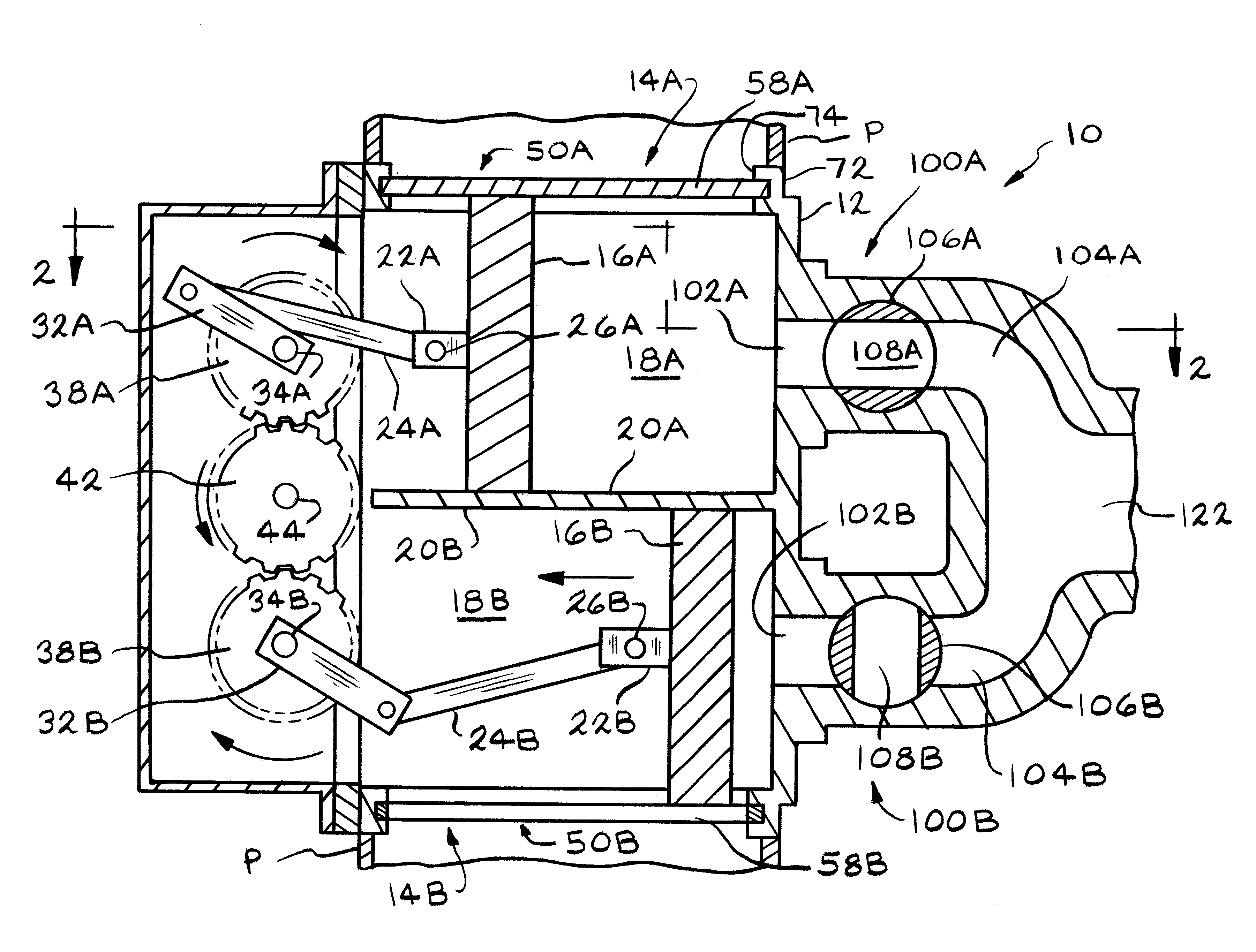
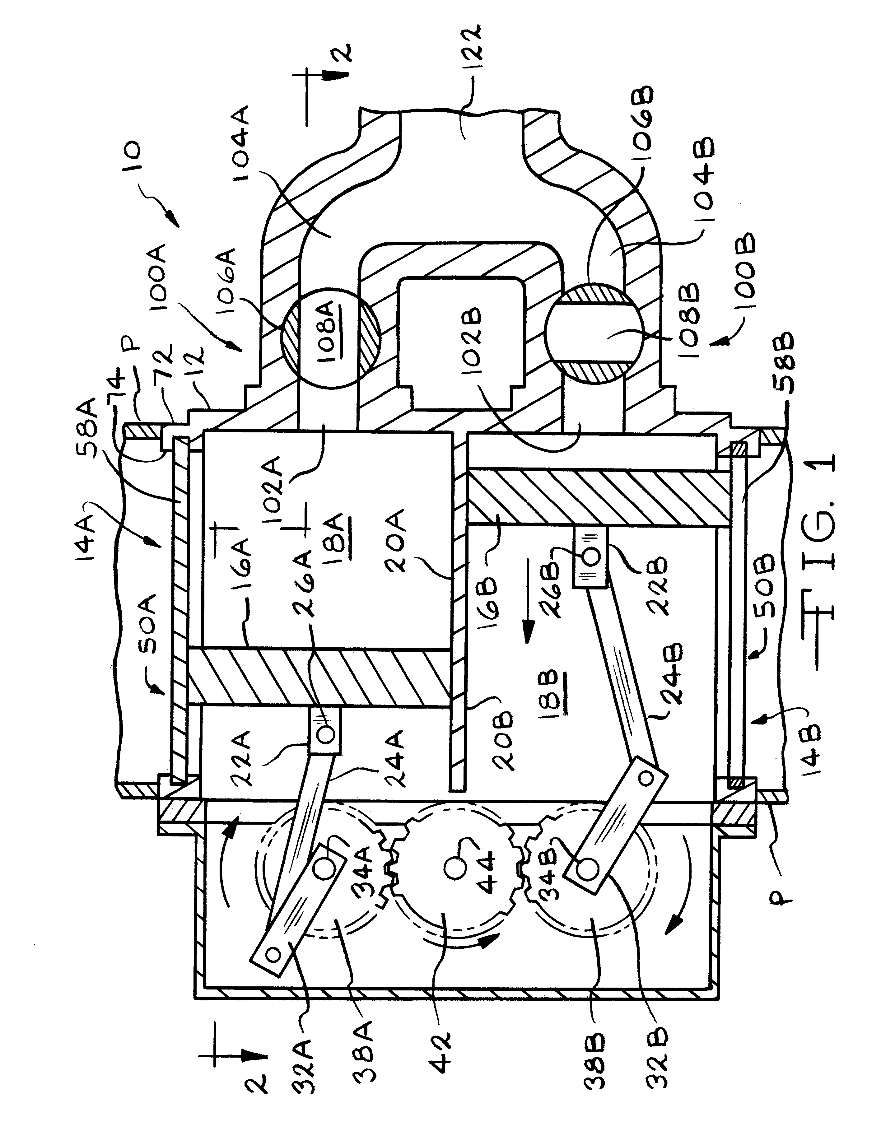
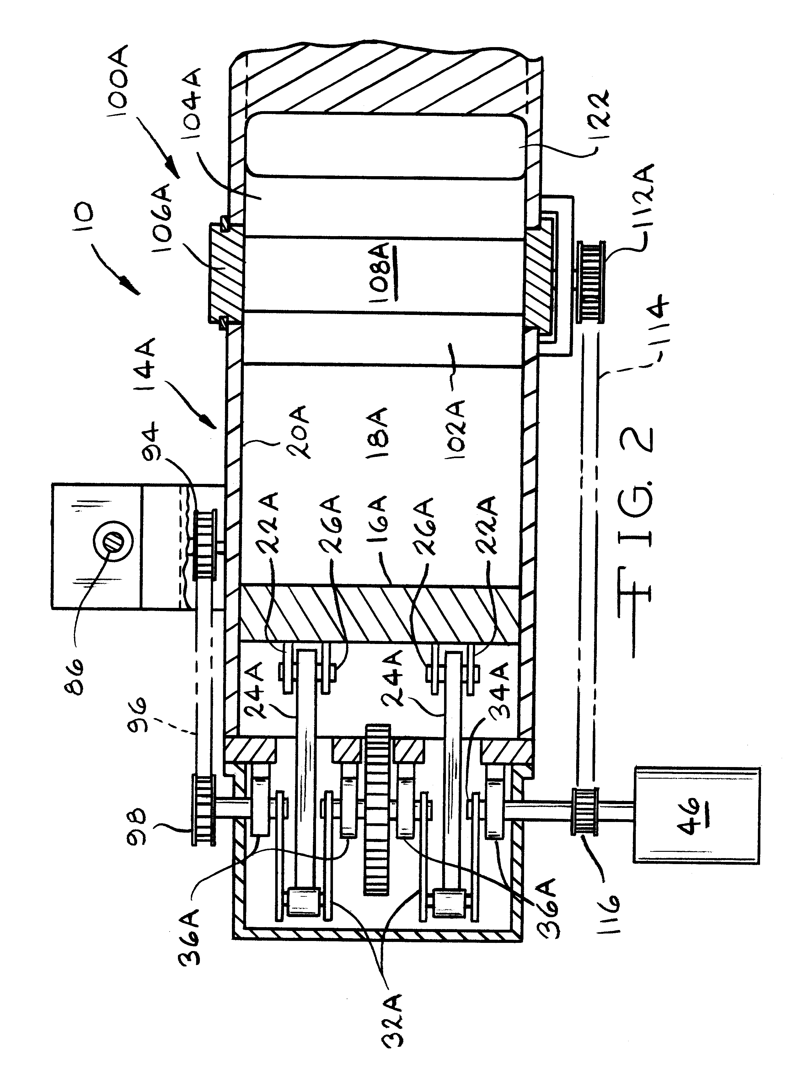
Referring now FIGS. 1 and 2, a controllable, high volume, positive displacement pump according to the present invention is illustrated and generally designated by the reference number 10. The positive displacement pump 10 includes a housing 12 which is preferably cast metal and includes various apertures, surfaces and ports which cooperate with other features of the invention. Specifically, the positive displacement pump 10 includes an upper or first piston and cylinder assembly 14A and a lower or second piston and cylinder assembly 14B. The upper piston and cylinder assembly 14A and the lower piston and cylinder assembly 14B are substantially identical and the upper piston and cylinder assembly 14A includes a first preferably rectangular piston 16A disposed within a complementary first rectangular cylinder 18A defined by a first rectangular cylinder wall 20A. The piston 16A includes a first pair of devises 22A which receive a respective first pair of connecting rods 24A which are p...


PUM


Abstract

A controllable positive displacement pump for liquids and gases which may contain dispersed phase particles includes a pair of pistons operating out of phase. Each of the pistons is associated with an inlet valve which includes a fixed grating defining slots which extend parallel to piston travel and a complementarily configured grating which reciprocates transversely in timed relationship with the piston to control the influx of fluid. A rotary outlet valve is also associated with each piston and includes a rotating member disposed transversely across the cylinder head and which rotates in synchronism to open a through, radial port in the member in timed relationship to the piston travel. The positive displacement pump finds particular application to transport powder paint.

Description

BACKGROUND OF THE INVENTIONThe invention relates generally to positive displacement pumps for liquids and gases and more specifically to a controllable positive displacement pump having a pair of pistons operating out of phase and specially configured and controllable inlet valves.Positive displacement pumps for liquids and gases typically include one or more piston and cylinder assemblies and associated inlet and outlet valves which control the flow of pumped fluid into and out of the cylinders. Such pumps are typically capable of relatively high pressure rise operation. A drawback of such positive displacement pumps is that both the inflow and outflow are distinctly pulsatile in character and, especially with high pressure pumps, the flow rates are generally relatively small.Furthermore, the ability to adjust pressure and flow rates with such pump can be problematic. Typically, of course, flow rates may be adjusted simply by reducing the speed of the pump. However, such a speed re...

Claims


Application Information

Patent Timeline
IPC IPC(8): F04B7/00
CPCF04B7/00Y10T137/86928Y10T137/1026
Inventor FOSS, JOHN F.
Owner FOSS JOHN F
Why Eureka
Eureka Blog
Learn More