Eureka AIR delivers breakthrough ideas for toughest innovation challenges, trusted by R&D personnel around the world.

Adjustment riser

Inactive Publication Date: 2001-03-06
IM2 MERCHANDISING & MFG
View PDF9 Cites 46 Cited by
  • Summary
  • Abstract
  • Description
  • Claims
  • Application Information

AI Technical Summary

Benefits of technology

It is a further object of this invention to provide such adjustment risers which matingly engage to provide lateral stability between adjacent mating risers.
The compression molded body has resilience and flexibility and can be physically compressed in a limited way.

Problems solved by technology

The adjustment riser has two functions, first it occupies the gap between the lower structure and the frame assembly to complete the assembly of the manhole or catch basin, and secondly it absorbs mechanical vibrations developed above the frame assembly, such as by vehicles travelling over the metal cover when the hole is located in a road, and inhibits transmission of the mechanical vibrations to the lower structure, which mechanical vibrations would otherwise cause fractures or cracking in a concrete riser as the lower structure, shortening its life such that frequent repair or replacement becomes necessary.
Thick adjustment risers are heavy and difficult to handle.

Method used


Image

  • Adjustment riser
  • Adjustment riser
  • Adjustment riser

Examples


Embodiment Construction

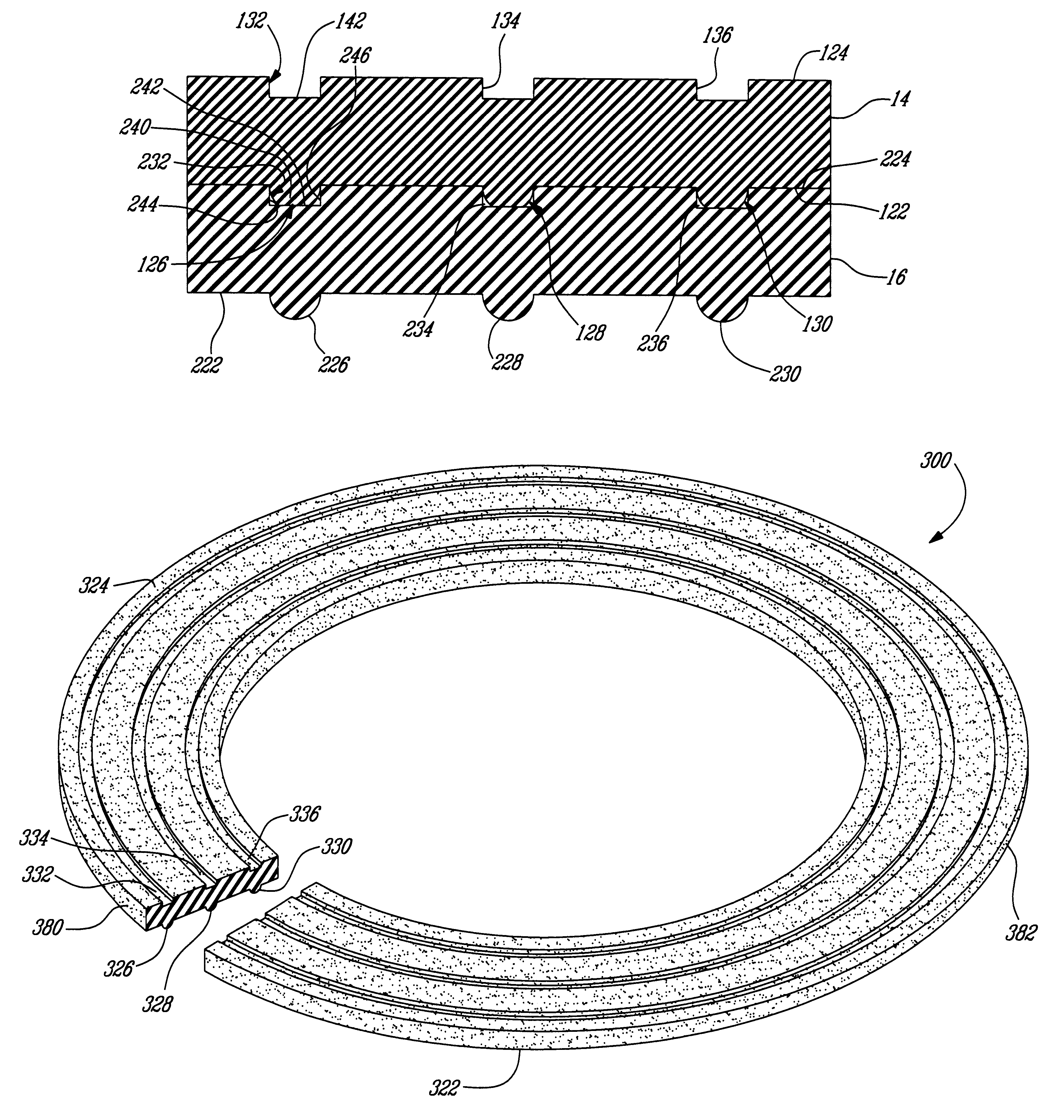
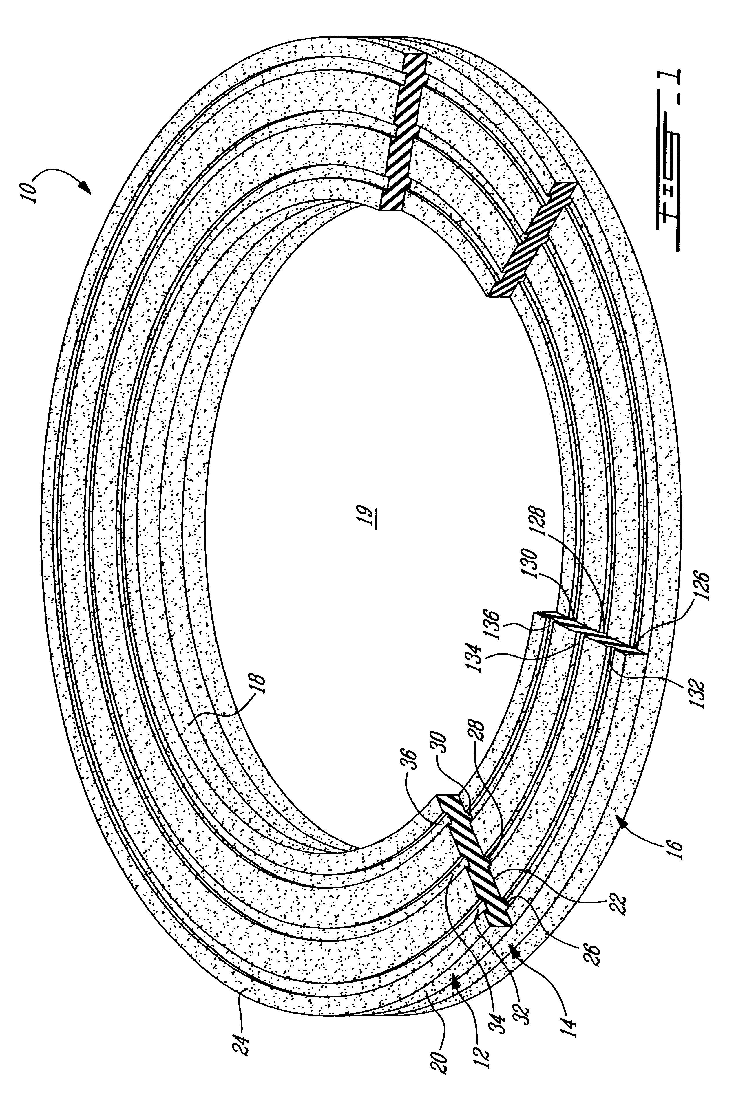
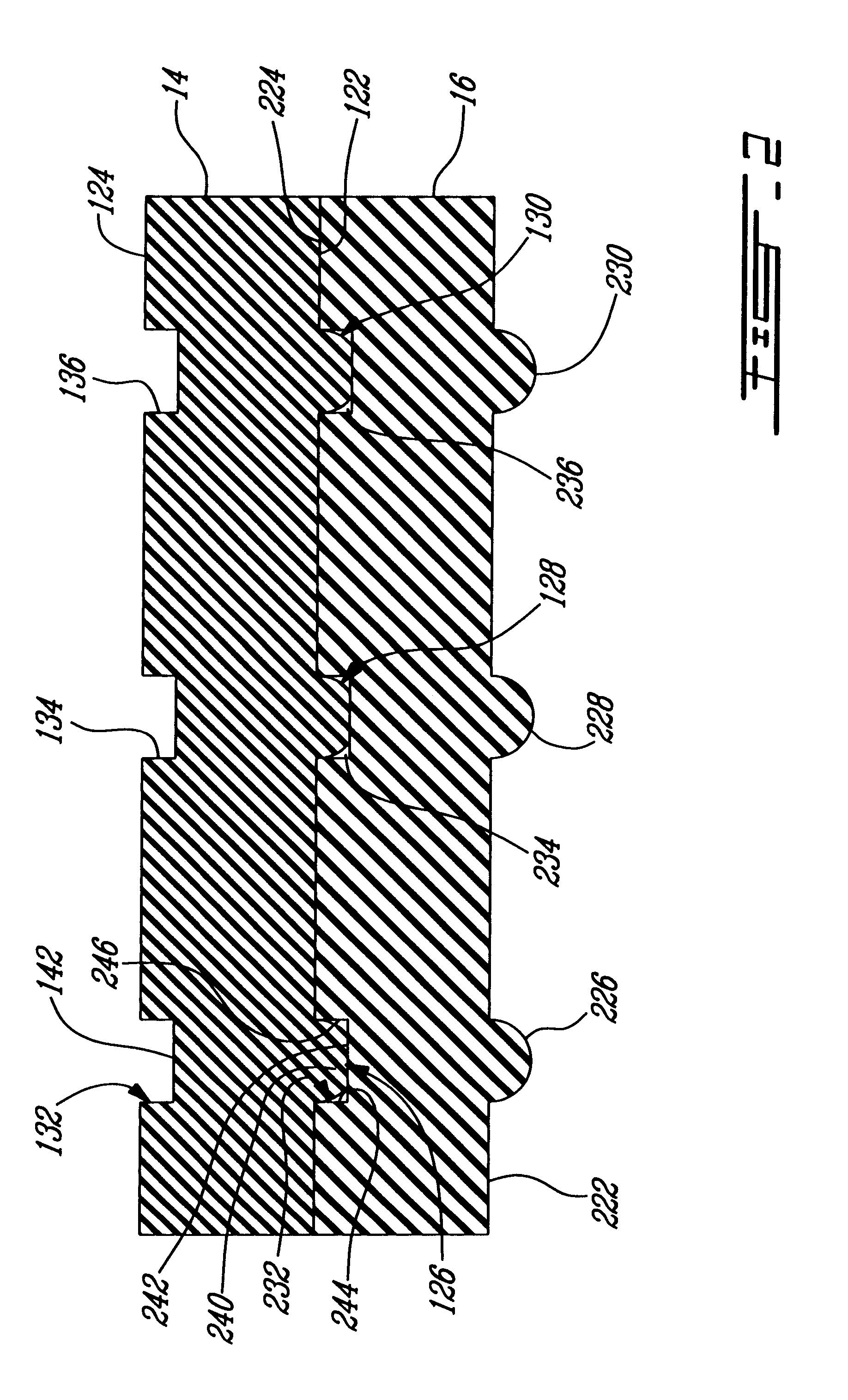
The adjustment riser of the invention may be of any ring-like configuration, including circular, elliptical or rectangular, but preferably is formed as an annular molded body. While the adjustment riser may have a single, continuous, elongate rib, and a corresponding single, continuous, elongate groove, in preferred embodiments there are a plurality of parallel, spaced apart ribs and a corresponding plurality of parallel spaced apart grooves.

In the preferred embodiment in which the molded body is annular, the ribs are concentric as are the grooves. Most suitably there are 1 to 5, and preferably 2 to 5 ribs and the same number of grooves, in a particular riser.

The first and second faces of the adjustment riser will be parallel in many cases, however, it is also advantageous to have risers in which one of the first and second faces lies in a plane inclined at an acute angle to a plane containing the other of the faces, such that the riser is of a wedge shape.

Preferably each rib is con...


PUM


Abstract

Adjustment risers for use in a manhole or catch basin, between a lower support structure, for example, a concrete riser, and an upper frame assembly, adjacent a surface in which the hole is formed, have a molded body and typically are annular; one or more ribs extend outwardly from a first sealing face and a corresponding one or more grooves are formed in an opposed second sealing face, each groove being in opposed relationship with a rib, whereby the adjustment risers may be matingly stacked to provide a required adjustment riser height for a specified manhole or catch basin.

Description

a) Field of the InventionThis invention relates to adjustment risers, and more especially to such risers which in use are matingly stacked to occupy a gap between a lower support structure and an upper frame assembly, especially in a manhole or catch basin. This invention further relates to an adjustment riser assembly; an assembly of a lower support structure an upper frame assembly and a stacked multiplicity of risers of the invention; and a method of inhibiting transmission of mechanical vibrations through an upper frame assembly to an adjacent lower support structure.b) Description of Prior ArtManholes which provide access to sewers or utility components, and catch basins for removal of rainwater, typically employ a lower support structure, for example, a concrete riser, a frame assembly typically of metal above the lower structure and a removable cover typically of metal to close and permit access to the lower structure and a conduit network communicating with the concrete rise...

Claims


Application Information

Patent Timeline
IPC IPC(8): E02D29/14
CPCE02D29/1409
Inventor SINCLAIR, DAVID BRENT
Owner IM2 MERCHANDISING & MFG
Why Eureka
Eureka Blog
Learn More