
Incoherent doppler laser detection and ranging system

a laser telescope and incoherent technology, applied in the field of incoherent laser telescope systems, can solve the problems of limited power received, limited mechanical stability of such equipment, and low amount of power received, so as to achieve better use

Inactive Publication Date: 2001-01-30
EUROPEAN SPACE AGENCY
View PDF4 Cites 51 Cited by
  • Summary
  • Abstract
  • Description
  • Claims
  • Application Information

AI Technical Summary

Benefits of technology

An object of the present invention is to provide a Lidar type incoherent laser telescope system that enables better use to be made of the power that is received.
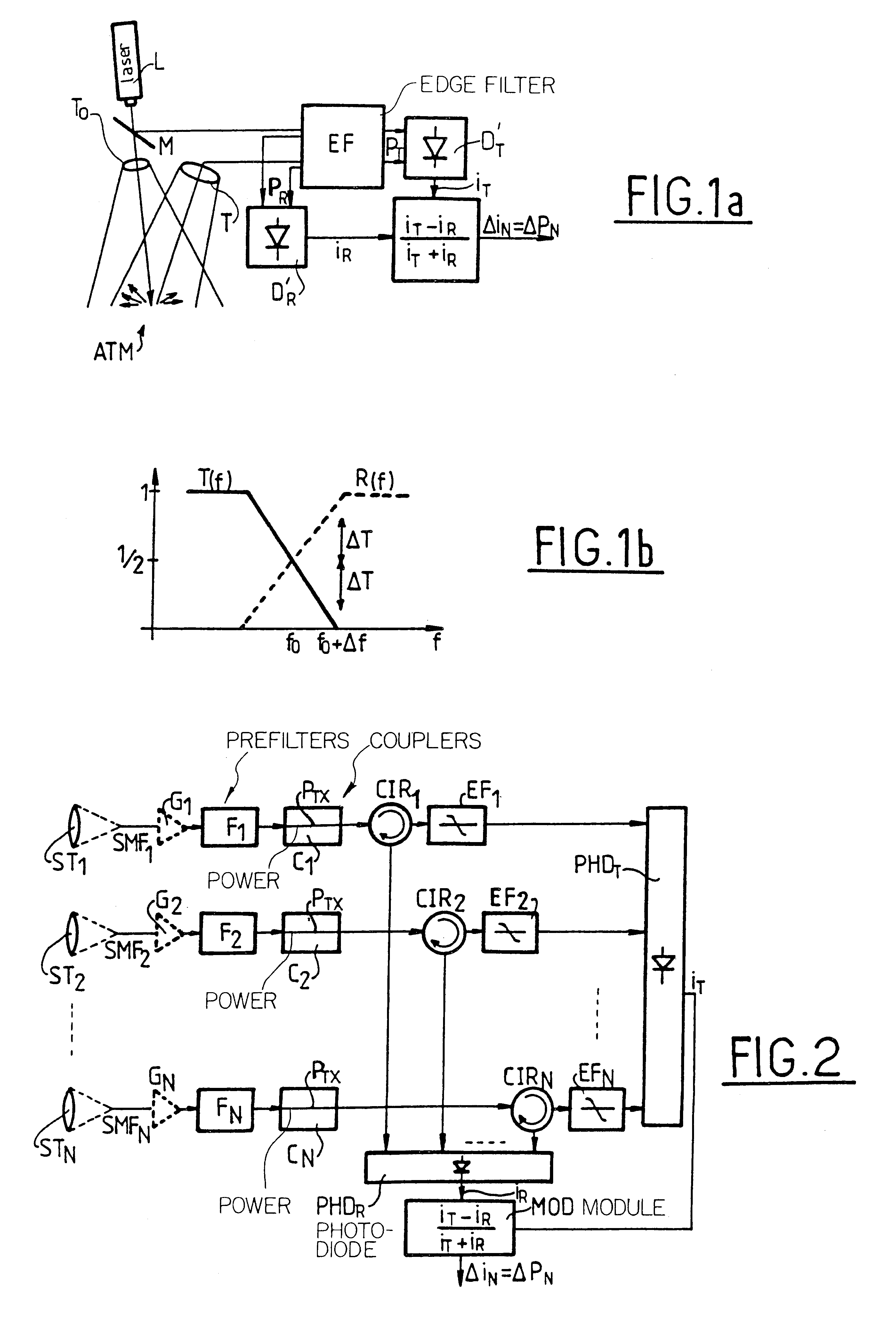
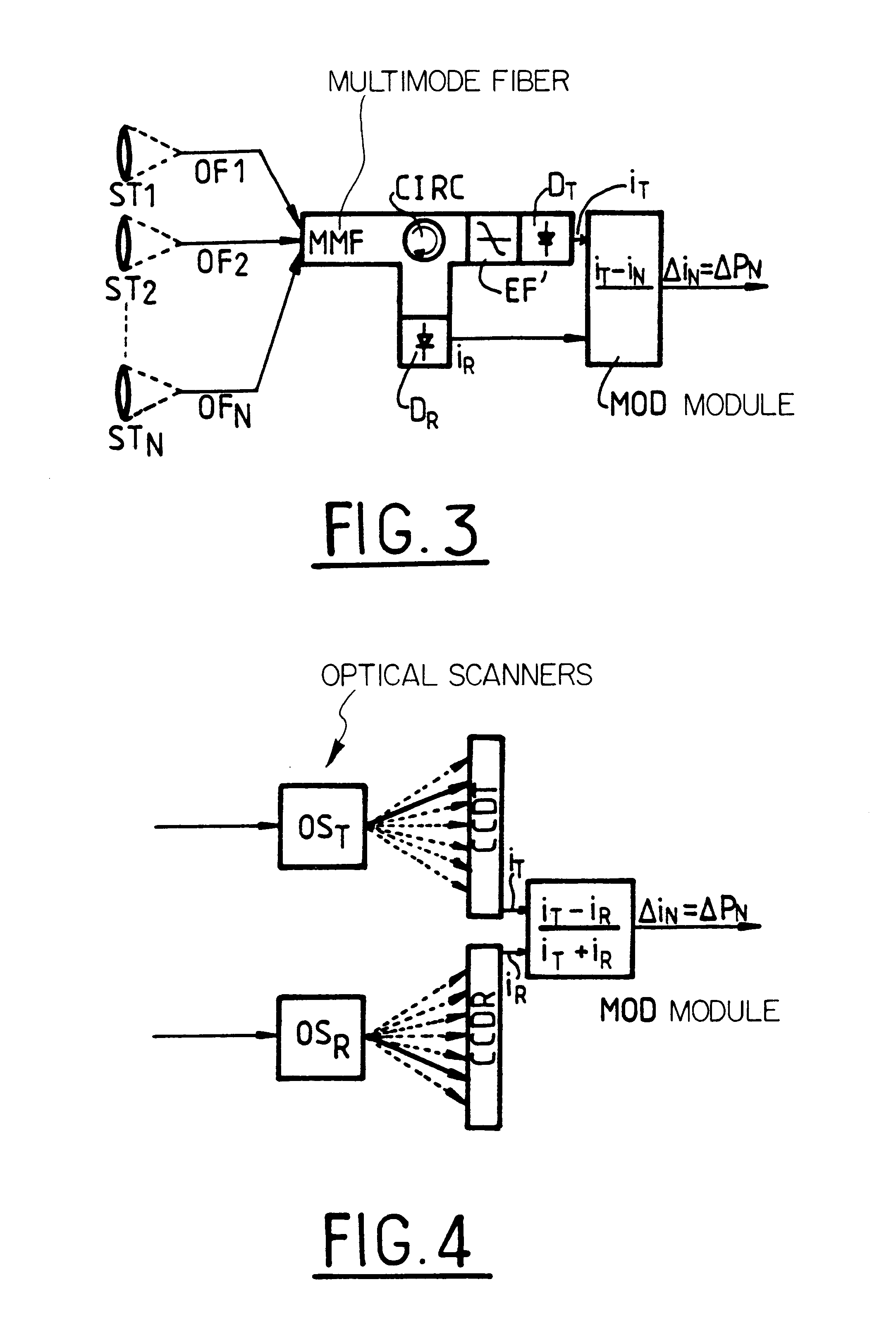
In a first variant, the optical fibers are monomode, and each branch includes an optical circulator each having a first outlet applied to an edge filter with a transmission outlet, and each having a second outlet constituting a reflection outlet. The transmission outlet of each edge filter can then be coupled to one of the N inlets of a first photodetector which outputs a current i.sub.T proportional to the transmitted power P.sub.T, and the second outlet of each optical circulator can be applied to one of the N inlets of a second photodetector which outputs a current i.sub.R proportional to the reflected power P.sub.R. Each branch may include a prefilter for filtering at least the molecular component of backscattering, the filter being disposed upstream from the corresponding optical circulator. It is preferable for each of the first and second photodetectors to include such a prefilter, thereby making it possible to implement only two filters, instead of N filters.

Problems solved by technology

Incoherent Lidar type systems suffer from technical problems associated with:
constraints on the mechanical stability of such equipment, in particular when on board a satellite.
In the particular case of an IDWL type Lidar, two additional problems can arise:
That technique suffers from the drawback of using only a portion of the backscattered power that it receives, and in addition, another portion of said received power is used for normalizing the signal.
Unfortunately, as mentioned above, the power received is limited by the size of the receiving telescope.
However, the amount of power received remains quite low and the problem of optimizing use of the received power remains and no solution is found for it.

Method used


Image

  • Incoherent doppler laser detection and ranging system
  • Incoherent doppler laser detection and ranging system
  • Incoherent doppler laser detection and ranging system

Examples


first embodiment

the invention, described below with reference to FIG. 2, makes use of monomode fibers. It uses N individual telescopes ST.sub.1, . . . , ST.sub.N whose outlets are coupled to a corresponding number of monomode fibers SMF.sub.1, . . . , SMF.sub.N. Downstream, the apparatus is based on optical fibers and includes optical prefilters F.sub.1, . . . , F.sub.N for eliminating the background noise due to radiation and for attenuating undesirable backscattered molecular components. A description of such a filter can be found in the article by K. W. Fischer entitled "Visible wavelength Doppler Lidar for measurement of wind and aerosol profiles during day and night", published Optical Engineering No. 34, 1995, pp. 499-511. Provision can also be made for couplers C.sub.1, . . . , C.sub.N for enabling a fraction of the power P.sub.TX as emitted directly by the laser L to be introduced into the apparatus. This is required for the reference measurement only when the edge filter cannot be locked o...


PUM


Abstract

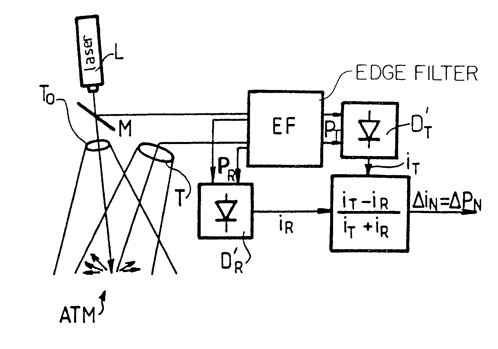
The invention relates to an incoherent Doppler laser detection and ranging system of the Lidar type comprising an emission laser and a receiver device including at least one telescope, an edge filter, and processor means responsive to the power PT transmitted by the filter. The processor means has data inputs relating to the power PT and to the power PR and outputs a normalized signal DELTAPN, where:PR designating the power reflected by the edge filter.

Description

In conventional manner, such apparatus comprises an emission laser and a receiver that includes an edge filter together with means for processing on the basis of the power P.sub.T transmitted through the filter. One particular known use lies in incoherent Doppler wind Lidar (IDWL) for detecting wind.Incoherent Lidar type systems suffer from technical problems associated with:the low level of power received which is due specifically to the size of the receive telescope, with the upper limit on said size being determined by considerations of mass and expense, and correspondingly by effective use of the power received;the alignment constraints on the numerous solid components as required by conventional systems; andconstraints on the mechanical stability of such equipment, in particular when on board a satellite.In the particular case of an IDWL type Lidar, two additional problems can arise:the effect of the return signal being subject to dispersion in the atmosphere, known as "speckle...

Claims


Application Information

Patent Timeline
Patent Type & Authority Patents(United States)
IPC IPC(8): G01S17/58G01S17/00
CPCG01S17/58
Inventor POPESCU, ALEXANDRU FLORINWINZER, PETER JOHANNES
Owner EUROPEAN SPACE AGENCY
Learn More