Infrared telescope with harmonization of the input and output axes

a technology of infrared telescope and input and output axes, applied in the field of infrared telescope, can solve the problems of nevertheless having a particular difficulty

Inactive Publication Date: 2001-01-23
THOMSON CSF SA
View PDF20 Cites 2 Cited by
  • Summary
  • Abstract
  • Description
  • Claims
  • Application Information

AI Technical Summary

Problems solved by technology

Embodiments of this type of telescope exist but they nevertheless have a particular difficulty.

Method used


Image

  • Infrared telescope with harmonization of the input and output axes
  • Infrared telescope with harmonization of the input and output axes
  • Infrared telescope with harmonization of the input and output axes

Examples


Embodiment Construction

With a view to simplicity in the different figures, the same objects bear the same topological references.

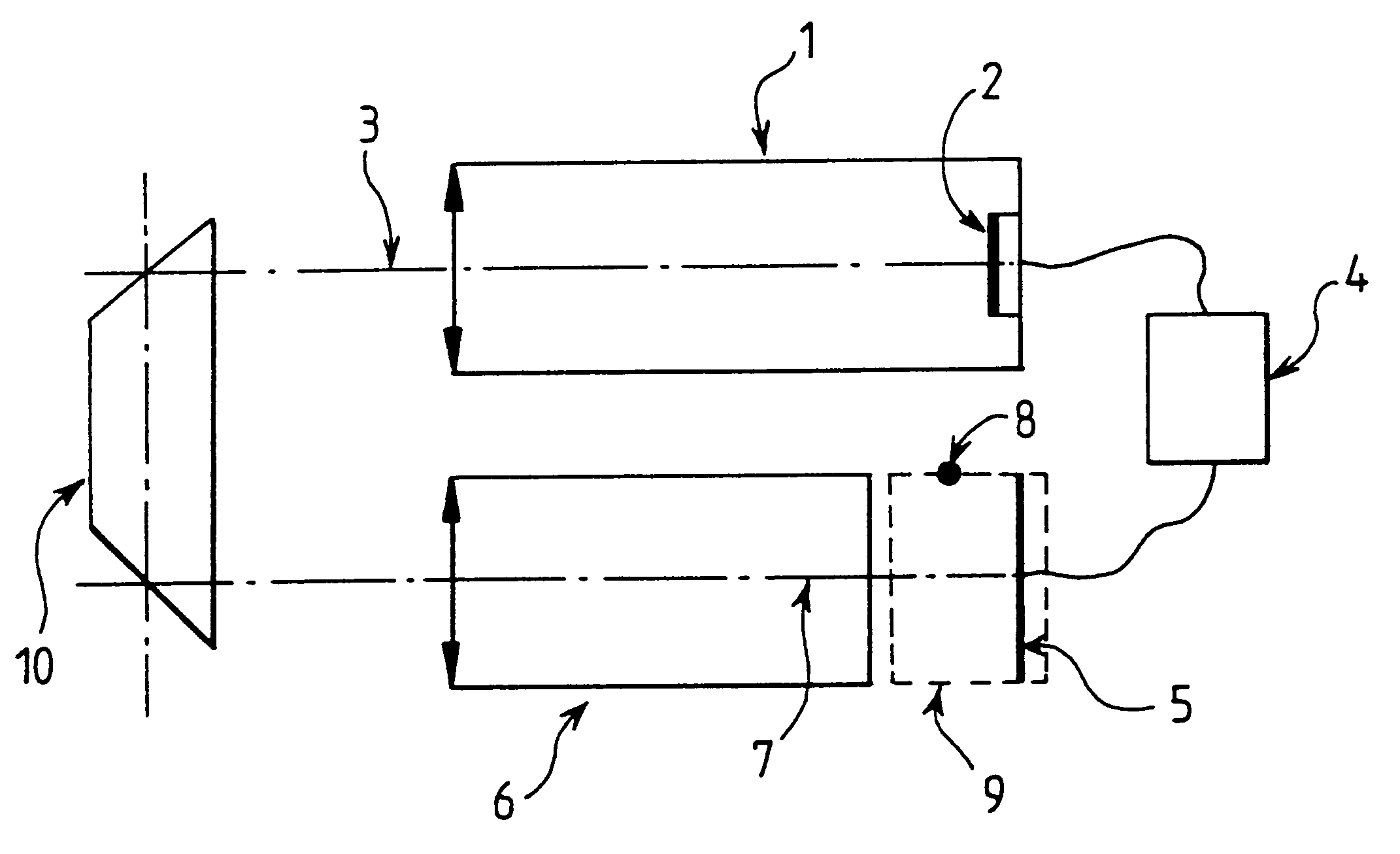
FIG. 1 shows the general principle of harmonization of the input axis 3 and output axis 7 of an infrared telescope with a magnification of unity, these two axes being parallel. The infrared telescope has an infrared camera 1 whose sighting axis is the input axis 3, a display screen 5 and a collimator 6 whose optical axis constitutes the output axis 7. A light ray coming out of the telescope along the output axis 7 has a direction opposite the direction of a ray entering along the input axis 3. It is clear that the invention is not limited to this configuration and that it can be implemented in any telescope, whatever the relative position of the input and output axes. However, this type of configuration is advantageously used in combination with a day telescope not shown in this figure. The two telescopes, namely the day telescope and the infrared telescope, are positioned in su...


PUM


Abstract

An infrared telescope, an apparatus for the harmonizing of its input and output axes including an infrared camera enabling the observation of an infrared scene and delivering a video signal representing the infrared scene, the infrared camera having a sighting axis that constitutes the input axis; a display screen receiving the video signal and displaying the corresponding image in the visible frequency spectrum; a bispectral, visible and infrared collimator, collimating the image displayed on the display screen at infinity, the collimator having an optical axis that constitutes the output axis; an infrared source positioned in a predefined way with respect to the output axis and positioned so that its radiation is collimated at infinity by the collimator; an element the reflection of the radiation coming from the infrared source at output of the collimator towards the infrared camera, the element enabling the formation on the display screen of an image of the infrared source; a device to measure the shift between the predefined position of the infrared source and the image of the infrared source on the display screen; and a device adjusting the telescope to reduce the shift.

Description

1. Field of the InventionThe invention relates to an infrared telescope comprising means to harmonize its input and output axes. It may be recalled that the telescope is a device used to observe a distant scene. The telescope gives an image of the scene at infinity. By analogy, an infrared telescope enables the observation of an infrared scene and gives an image thereof that is visible at infinity.Many sighting systems such as for example a gun sighting device, a laser telemeter or a missile firing station use a telescope working in the visible light spectrum. This telescope, called a day telescope, defines an axis by means of a reticule. It may be necessary to make these sighting systems work in a frequency spectrum other than the visible spectrum, such as for example the infrared spectrum. A usual frequency band of the infrared spectrum ranges for example between about three and five .mu.m. Another band commonly used in the infrared spectrum is located approximately between eight ...

Claims


Application Information

Patent Timeline
Patent Type & Authority Patents(United States)
IPC IPC(8): G02B23/00G02B23/12
CPCG02B23/12
Inventor FOUILLOY, JEAN-PIERRESEUGNET, PATRICK
Owner THOMSON CSF SA
Why Eureka
Try Eureka